
Introduction to 4×4 Keypads
A 4×4 keypad is a matrix-style input device commonly used in electronic projects, such as microcontroller-based systems, to provide a user-friendly interface for data entry. This in-depth keypad guide will cover the fundamentals of 4×4 keypads, their working principle, interfacing with microcontrollers, and practical applications.
What is a 4×4 Keypad?
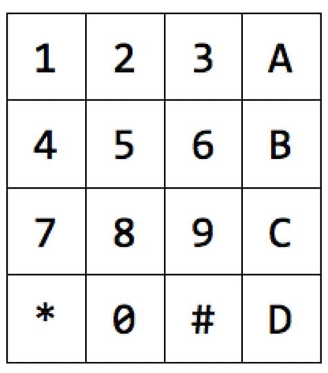
A 4×4 keypad consists of 16 buttons arranged in a 4×4 matrix. Each button represents a unique character or function, typically including numbers 0-9, letters A-D, and symbols like ‘#’ and ‘*’. The compact and intuitive layout makes it an ideal input device for various applications.
Advantages of using 4×4 Keypads
- User-friendly interface
- Compact size
- Low cost
- Easy to interface with microcontrollers
- Suitable for a wide range of applications
Understanding the 4×4 Keypad Matrix
Keypad Matrix Structure
A 4×4 keypad utilizes a matrix structure to minimize the number of input/output (I/O) pins required for interfacing. The matrix consists of four rows and four columns, with each button connected between a unique row and column.
| Column 1 | Column 2 | Column 3 | Column 4 | |
|---|---|---|---|---|
| Row 1 | 1 | 2 | 3 | A |
| Row 2 | 4 | 5 | 6 | B |
| Row 3 | 7 | 8 | 9 | C |
| Row 4 | * | 0 | # | D |
Keypad Scanning Technique
To detect button presses, a keypad scanning technique is employed. The microcontroller sends a logic level (usually LOW) to each row sequentially while monitoring the columns for a change in logic level. When a button is pressed, it connects the corresponding row and column, allowing the microcontroller to identify the pressed key.
Interfacing 4×4 Keypad with Microcontrollers
Hardware Connection
To interface a 4×4 keypad with a microcontroller, you need to connect the row and column pins to the microcontroller’s I/O pins. Typically, the rows are configured as outputs, and the columns are configured as inputs with pull-up resistors.
| Keypad Pin | Microcontroller Pin |
|---|---|
| Row 1 | PB0 |
| Row 2 | PB1 |
| Row 3 | PB2 |
| Row 4 | PB3 |
| Column 1 | PB4 |
| Column 2 | PB5 |
| Column 3 | PB6 |
| Column 4 | PB7 |
Software Implementation
The software implementation for keypad scanning involves the following steps:
- Configure the row pins as outputs and the column pins as inputs with pull-up resistors.
- Set all row pins to HIGH.
- Scan each row by setting it to LOW and checking the state of the column pins.
- If a column pin goes LOW, a button press is detected at the corresponding row and column intersection.
- Debounce the button press to avoid false triggers.
- Process the detected button press according to the application requirements.
Here’s a sample code snippet for keypad scanning using Arduino:
const byte ROWS = 4;
const byte COLS = 4;
char keys[ROWS][COLS] = {
  {'1', '2', '3', 'A'},
  {'4', '5', '6', 'B'},
  {'7', '8', '9', 'C'},
  {'*', '0', '#', 'D'}
};

byte rowPins[ROWS] = {9, 8, 7, 6};
byte colPins[COLS] = {5, 4, 3, 2};

void setup() {
  Serial.begin(9600);
  for (byte i = 0; i < ROWS; i++) {
    pinMode(rowPins[i], OUTPUT);
    digitalWrite(rowPins[i], HIGH);
  }
  for (byte i = 0; i < COLS; i++) {
    pinMode(colPins[i], INPUT_PULLUP);
  }
}

void loop() {
  char key = getKey();
  if (key != '\0') {
    Serial.println(key);
  }
}

char getKey() {
  for (byte rowIndex = 0; rowIndex < ROWS; rowIndex++) {
    digitalWrite(rowPins[rowIndex], LOW);
    for (byte colIndex = 0; colIndex < COLS; colIndex++) {
      if (digitalRead(colPins[colIndex]) == LOW) {
        delay(10); // Debounce delay
        while (digitalRead(colPins[colIndex]) == LOW);
        return keys[rowIndex][colIndex];
      }
    }
    digitalWrite(rowPins[rowIndex], HIGH);
  }
  return '\0';
}

Practical Applications of 4×4 Keypads
Access Control Systems
4×4 keypads are commonly used in access control systems, such as door locks and security panels. Users can enter a predefined code or password using the keypad to gain access to a restricted area or device.
Calculator and Data Entry Devices
Keypads are essential components in calculator projects and data entry devices. They provide a convenient way for users to input numerical data, perform calculations, or enter alphanumeric information.
Menu-driven User Interfaces
In projects with menu-driven user interfaces, 4×4 keypads allow users to navigate through menu options, select desired functions, and input required parameters. This is particularly useful in embedded systems and DIY projects.
Home Automation and Remote Control
4×4 keypads can be integrated into home automation systems and remote control projects. Users can enter commands or codes using the keypad to control various devices, such as lights, appliances, or multimedia systems.

Troubleshooting and Common Issues
Keypad Not Responding
If the keypad is not responding, check the following:
- Ensure proper connections between the keypad and the microcontroller.
- Verify that the row and column pins are configured correctly in the software.
- Check for any loose or broken connections.
- Test the keypad with a multimeter to ensure button functionality.
Multiple Button Presses Detected
If multiple button presses are detected simultaneously, it could be due to:
- Insufficient debounce delay in the software.
- Faulty or worn-out keypad buttons.
- Incorrect pull-up resistor configuration.
To resolve this issue, increase the debounce delay, replace the faulty keypad, or check the pull-up resistor connections.
Frequently Asked Questions (FAQ)
1. Can I use a 4×4 keypad with any microcontroller?
Yes, you can use a 4×4 keypad with any microcontroller that has sufficient I/O pins available. The interfacing process remains similar across different microcontroller platforms.
2. How do I clean my 4×4 keypad?
To clean your 4×4 keypad, use a soft, damp cloth with mild detergent. Avoid using abrasive materials or excessive water, as it may damage the keypad or cause electrical issues.
3. Can I customize the characters on a 4×4 keypad?
Some 4×4 keypads come with pre-printed characters, while others have removable keycaps that allow for customization. You can replace the keycaps with custom-printed ones or use labels to change the characters according to your application requirements.
4. How long do 4×4 keypads typically last?
The lifespan of a 4×4 keypad depends on factors such as usage frequency, environmental conditions, and manufacturing quality. On average, a well-maintained keypad can last for several years under normal use.
5. Are there any alternatives to 4×4 keypads?
Yes, there are alternative input devices that can be used depending on the application requirements. Some options include:
- Membrane keypads
- Capacitive touch keypads
- Touchscreens
- Rotary encoders
- Joysticks or navigation switches
Conclusion
This in-depth guide has provided a comprehensive overview of 4×4 keypads, covering their working principle, interfacing with microcontrollers, practical applications, troubleshooting, and frequently asked questions. By understanding the fundamentals of 4×4 keypads, you can effectively incorporate them into your projects and create user-friendly interfaces for data entry and control.
As you explore the world of 4×4 keypads, remember to consider factors such as keypad quality, software debouncing, and proper hardware connections to ensure optimal performance and reliability. With the knowledge gained from this guide, you are well-equipped to tackle various projects involving 4×4 keypads and expand your skills in embedded systems and user interface design.
No responses yet