Introduction to Stripline and Microstrip
In the world of high-frequency electronics, the choice of signal transmission lines plays a crucial role in ensuring the integrity and efficiency of the system. Two commonly used transmission line structures are stripline and microstrip. Both stripline and microstrip are planar transmission lines that are widely employed in microwave circuits, printed circuit boards (PCBs), and radio frequency (RF) applications. However, they differ in their structure, characteristics, and suitability for various design requirements.
This article aims to provide a comprehensive comparison between stripline and microstrip, exploring their fundamental principles, advantages, disadvantages, and applications. By understanding the key differences between these two transmission line structures, designers and engineers can make informed decisions when selecting the most appropriate option for their specific high-frequency signal transmission needs.
What is Stripline?
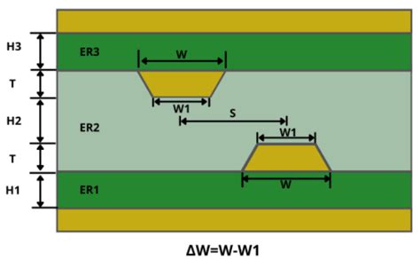
Stripline is a transmission line structure that consists of a flat conductor strip sandwiched between two parallel ground planes. The conductor strip is typically embedded in a dielectric material, which provides insulation and determines the characteristic impedance of the stripline. The width of the conductor strip and the thickness of the dielectric material are carefully designed to achieve the desired impedance and signal propagation characteristics.
What is Microstrip?
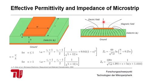
Microstrip, on the other hand, is a transmission line structure that consists of a flat conductor strip placed on top of a dielectric substrate, with a ground plane on the opposite side of the substrate. The conductor strip is exposed to the air on one side, while the dielectric material separates it from the ground plane. The width of the conductor strip, the thickness of the dielectric substrate, and the dielectric constant of the substrate material determine the characteristic impedance and signal propagation properties of the microstrip.
Structural Differences Between Stripline and Microstrip
One of the primary differences between stripline and microstrip lies in their physical structure. Let’s take a closer look at the structural characteristics of each transmission line.
Stripline Structure
Stripline has a symmetrical structure, with the conductor strip positioned in the center of the dielectric material, equidistant from the two ground planes. This symmetrical arrangement provides several advantages:
- Shielding: The conductor strip is completely enclosed by the ground planes, offering excellent shielding against external electromagnetic interference (EMI) and crosstalk.
- Controlled impedance: The characteristic impedance of stripline is determined by the width of the conductor strip and the thickness and dielectric constant of the dielectric material. The symmetrical structure allows for precise control over the impedance.
- Reduced radiation: Since the conductor strip is surrounded by the ground planes, stripline exhibits minimal radiation losses, making it suitable for applications where signal integrity is critical.
Microstrip Structure
Microstrip has an asymmetrical structure, with the conductor strip placed on top of the dielectric substrate and exposed to air on one side. The ground plane is located on the opposite side of the substrate. This asymmetrical arrangement has the following implications:
- Ease of fabrication: Microstrip is relatively easier to fabricate compared to stripline, as it involves a single-layer structure with the conductor strip and ground plane on opposite sides of the substrate.
- Accessibility: The conductor strip in microstrip is easily accessible for component placement, making it convenient for circuit integration and modifications.
- Dispersion: Due to the asymmetrical structure and the presence of air on one side, microstrip is more susceptible to dispersion effects, especially at higher frequencies.
| Parameter | Stripline | Microstrip |
|---|---|---|
| Structure | Symmetrical | Asymmetrical |
| Conductor Position | Embedded in dielectric | On top of substrate |
| Ground Planes | Two (top and bottom) | One (bottom) |
| Shielding | Excellent | Good |
| Impedance Control | Precise | Good |
| Radiation Losses | Minimal | Moderate |
| Fabrication | More complex | Simpler |
| Accessibility | Limited | Easy |
| Dispersion | Low | Moderate to high |
 Stripline-MicrostripComparison-ddf1affbe34b11ee92aef7f8ca593eb4.jpeg” alt=”” class=”wp-image-136″ srcset=”https://electronicmanufacturingservice.org/wp-content/uploads/2024/03/Stripline-MicrostripComparison-ddf1affbe34b11ee92aef7f8ca593eb4.jpeg”>
Characteristic Impedance and Signal Propagation
The characteristic impedance and signal propagation properties of stripline and microstrip are influenced by their structural differences and the materials used.
Stripline Characteristic Impedance
The characteristic impedance of stripline is determined by the following factors:
– Width of the conductor strip
– Thickness of the dielectric material
– Dielectric constant of the dielectric material
The characteristic impedance of stripline can be calculated using the following equation:
Z₀ = (60 / √ε_r) * ln(4h / 0.67πw)
Where:
– Z₀ is the characteristic impedance in ohms
– ε_r is the relative dielectric constant of the dielectric material
– h is the thickness of the dielectric material
– w is the width of the conductor strip
Microstrip Characteristic Impedance
The characteristic impedance of microstrip depends on the following factors:
– Width of the conductor strip
– Thickness of the dielectric substrate
– Dielectric constant of the substrate material
The characteristic impedance of microstrip can be approximated using the following equations:
For w/h ≤ 1:
Z₀ = (60 / √ε_eff) * ln(8h / w + 0.25w / h)
For w/h > 1:
Z₀ = (120π / √ε_eff) / [w/h + 1.393 + 0.667 ln(w/h + 1.444)]
Where:
– Z₀ is the characteristic impedance in ohms
– ε_eff is the effective dielectric constant of the microstrip
– h is the thickness of the dielectric substrate
– w is the width of the conductor strip
Signal Propagation
The signal propagation characteristics of stripline and microstrip differ due to their structural differences and the presence of air in microstrip.
Stripline:
– Stripline provides a homogeneous dielectric environment, as the conductor strip is completely surrounded by the dielectric material.
– The signal propagation velocity in stripline is determined by the dielectric constant of the dielectric material.
– Stripline exhibits lower dispersion and lower losses compared to microstrip, especially at higher frequencies.
Microstrip:
– Microstrip has an inhomogeneous dielectric environment, with the conductor strip exposed to air on one side and the dielectric substrate on the other.
– The effective dielectric constant of microstrip is a combination of the dielectric constant of the substrate material and air.
– Microstrip exhibits higher dispersion and higher losses compared to stripline, particularly at higher frequencies, due to the presence of air and the inhomogeneous dielectric environment.
| Parameter | Stripline | Microstrip |
|---|---|---|
| Dielectric Environment | Homogeneous | Inhomogeneous |
| Dielectric Constant | Determined by dielectric material | Combination of substrate and air |
| Dispersion | Lower | Higher |
| Losses | Lower | Higher |

Advantages and Disadvantages
Both stripline and microstrip have their own advantages and disadvantages, which should be considered when selecting the appropriate transmission line for a specific application.
Advantages of Stripline
- Excellent EMI Shielding: The conductor strip in stripline is surrounded by ground planes, providing superior shielding against external electromagnetic interference.
- Low crosstalk: The shielding properties of stripline also minimize crosstalk between adjacent signal traces, making it suitable for high-density circuit designs.
- Controlled impedance: Stripline allows for precise control over the characteristic impedance, enabling the design of well-matched and optimized signal paths.
- Low radiation losses: The enclosed structure of stripline minimizes radiation losses, ensuring efficient signal transmission.
- Suitability for multilayer designs: Stripline can be easily incorporated into Multilayer PCB designs, enabling compact and high-density circuit layouts.
Disadvantages of Stripline
- Complexity in fabrication: Stripline requires a more complex fabrication process compared to microstrip, as it involves embedding the conductor strip within the dielectric material.
- Limited accessibility: The conductor strip in stripline is not easily accessible for component placement or probing, making it less convenient for circuit modifications and debugging.
- Increased material cost: The use of additional dielectric material and the need for precise alignment of the conductor strip and ground planes can increase the overall material cost of stripline designs.
Advantages of Microstrip
- Ease of fabrication: Microstrip has a simpler fabrication process compared to stripline, as it involves a single-layer structure with the conductor strip and ground plane on opposite sides of the substrate.
- Accessibility for component placement: The conductor strip in microstrip is easily accessible, allowing for convenient component placement and circuit modifications.
- Lower material cost: Microstrip requires less dielectric material compared to stripline, potentially reducing the overall material cost of the design.
- Compatibility with surface-mount technology (SMT): Microstrip is well-suited for integrating surface-mount components, making it compatible with SMT assembly processes.
Disadvantages of Microstrip
- Higher radiation losses: The exposed conductor strip in microstrip can result in higher radiation losses compared to stripline, especially at higher frequencies.
- Susceptibility to EMI: Microstrip is more susceptible to external electromagnetic interference due to the exposed conductor strip.
- Dispersion effects: The inhomogeneous dielectric environment of microstrip can lead to higher dispersion effects, particularly at higher frequencies, which can impact signal integrity.
- Limited power handling capacity: Microstrip has a lower power handling capacity compared to stripline due to the exposed conductor strip and the potential for dielectric breakdown.
| Characteristic | Stripline | Microstrip |
|---|---|---|
| EMI Shielding | Excellent | Good |
| Crosstalk | Low | Moderate |
| Impedance Control | Precise | Good |
| Radiation Losses | Low | Moderate to high |
| Multilayer Suitability | Excellent | Good |
| Fabrication Complexity | Higher | Lower |
| Accessibility | Limited | Easy |
| Material Cost | Higher | Lower |
| SMT Compatibility | Limited | Excellent |
| Power Handling Capacity | Higher | Lower |
Applications and Design Considerations
The choice between stripline and microstrip depends on the specific requirements of the application and the design constraints. Let’s explore some common applications and design considerations for each transmission line structure.
Stripline Applications
Stripline is commonly used in the following applications:
1. High-speed digital circuits: Stripline’s excellent EMI shielding and controlled impedance make it suitable for high-speed digital signal transmission, such as in computer buses and backplanes.
2. Microwave circuits: Stripline’s low radiation losses and controlled impedance are beneficial for microwave circuits, including filters, couplers, and power dividers.
3. Multilayer PCBs: Stripline can be effectively utilized in multilayer PCB designs, enabling high-density signal routing and minimizing crosstalk between layers.
4. Aerospace and defense systems: Stripline’s shielding properties and controlled impedance make it suitable for aerospace and defense applications that require high signal integrity and EMI immunity.
Microstrip Applications
Microstrip finds applications in the following areas:
1. RF and wireless communication systems: Microstrip’s ease of fabrication and compatibility with surface-mount components make it widely used in RF and wireless communication circuits, such as amplifiers, mixers, and antennas.
2. Microwave integrated circuits (MICs): Microstrip is commonly employed in the design of microwave integrated circuits, where its accessibility and compatibility with active and passive components are advantageous.
3. Printed antennas: Microstrip is often used in the design of printed antennas, such as patch antennas, due to its planar structure and ease of integration with other circuit components.
4. Consumer electronics: Microstrip’s lower fabrication complexity and material cost make it suitable for mass-produced consumer electronic devices, such as smartphones, tablets, and wearable devices.
Design Considerations
When designing with stripline or microstrip, the following factors should be considered:
1. Frequency range: The desired frequency range of operation should be taken into account when selecting the transmission line structure. Stripline generally performs better at higher frequencies compared to microstrip due to its lower dispersion and radiation losses.
2. Impedance matching: Proper impedance matching is crucial for efficient signal transmission and minimizing reflections. The characteristic impedance of the transmission line should be matched to the impedance of the source and load to ensure optimal signal integrity.
3. Substrate selection: The choice of substrate material and its dielectric constant play a significant role in determining the characteristic impedance and signal propagation properties of the transmission line. Factors such as substrate thickness, dielectric loss, and thermal stability should be considered.
4. Trace geometry: The width and thickness of the conductor strip, as well as the spacing between the strip and ground planes (for stripline), should be carefully designed to achieve the desired characteristic impedance and signal integrity.
5. Grounding and shielding: Proper grounding and shielding techniques should be employed to minimize EMI, crosstalk, and radiation losses. Stripline inherently provides better shielding compared to microstrip, but appropriate grounding strategies should be implemented in both cases.
6. Manufacturing constraints: The fabrication capabilities and tolerances of the manufacturing process should be taken into account when designing with stripline or microstrip. Stripline’s embedded structure may require more precise alignment and tighter tolerances compared to microstrip.
Frequently Asked Questions (FAQ)
-
Q: What is the main difference between stripline and microstrip?
A: The main difference between stripline and microstrip lies in their physical structure. Stripline has a conductor strip sandwiched between two parallel ground planes, while microstrip has a conductor strip on top of a dielectric substrate with a single ground plane on the opposite side. -
Q: Which transmission line structure provides better EMI shielding?
A: Stripline provides better EMI shielding compared to microstrip due to its enclosed structure, where the conductor strip is surrounded by ground planes. This shielding property makes stripline less susceptible to external electromagnetic interference. -
Q: Is microstrip easier to fabricate compared to stripline?
A: Yes, microstrip is generally easier to fabricate compared to stripline. Microstrip involves a single-layer structure with the conductor strip and ground plane on opposite sides of the substrate, while stripline requires embedding the conductor strip within the dielectric material, which adds complexity to the fabrication process. -
Q: Which transmission line structure is more suitable for high-frequency applications?
A: Stripline is often preferred for high-frequency applications due to its lower dispersion and radiation losses compared to microstrip. The homogeneous dielectric environment and shielding properties of stripline make it suitable for maintaining signal integrity at higher frequencies. -
Q: Can both stripline and microstrip be used in multilayer PCB designs?
A: Yes, both stripline and microstrip can be used in multilayer PCB designs. Stripline is particularly well-suited for multilayer designs, as it can be easily incorporated between layers, providing shielding and minimizing crosstalk. Microstrip can also be used in multilayer designs but may require additional considerations for shielding and signal integrity.
Conclusion
In conclusion, stripline and microstrip are two fundamental transmission line structures used in high-frequency signal transmission. While both serve the purpose of guiding signals, they differ in their physical structure, characteristic impedance, signal propagation properties, and suitability for various applications.
Stripline offers excellent EMI shielding, low crosstalk, controlled impedance, and low radiation losses, making it suitable for high-speed digital circuits, microwave circuits, multilayer PCBs, and aerospace and defense systems. However, it comes with increased fabrication complexity, limited accessibility, and higher material costs.
On the other hand, microstrip provides ease of fabrication, accessibility for component placement, lower material costs, and compatibility with surface-mount technology. It finds applications in RF and wireless communication systems, microwave integrated circuits, printed antennas, and consumer electronics. However, microstrip is more susceptible to radiation losses, EMI, and dispersion effects compared to stripline.
When selecting between stripline and microstrip, designers must consider factors such as the frequency range of operation, impedance matching requirements, substrate properties, trace geometry, grounding and shielding techniques, and manufacturing constraints. By understanding the strengths and limitations of each transmission line structure, designers can make informed decisions to optimize signal integrity, minimize losses, and meet the specific requirements of their high-frequency applications.
As technology continues to advance and the demand for high-speed and high-frequency systems grows, the choice between stripline and microstrip will remain crucial in the design of efficient and reliable signal transmission lines. By leveraging the advantages of each structure and carefully considering the design trade-offs, engineers can ensure the successful implementation of high-performance electronic systems in various domains.
No responses yet