Introduction to the Hx711 Load Cell Amplifier
The Hx711 is a precision 24-bit analog-to-digital converter (ADC) designed for weigh scales and industrial control applications to interface directly with a bridge sensor. The Hx711 load cell amplifier is commonly used with load cells to measure weight in electronic scales, industrial weighing systems, and force sensing applications.
This article provides an in-depth look at the Hx711 datasheet, pinout configuration, key features, and usage instructions to help you effectively incorporate this chip into your projects. We’ll also cover some frequently asked questions about the Hx711.
Hx711 Chip Overview and Key Features
The Hx711 chip is a small, low-cost component that amplifies and digitizes the output of a load cell, enabling precise weight or force measurements. Some of its key features include:
- High-precision 24-bit analog-to-digital converter (ADC)
- Selectable 10 SPS or 80 SPS output data rate
- On-chip active low noise programmable gain amplifier (PGA) with selectable gain of 32, 64, and 128
- On-chip power supply regulator for load-cell and ADC analog power supply
- Operation supply voltage range from 2.6V to 5.5V
- Simple digital control and serial interface: pin-driven controls, no programming needed
- Selectable 10 Hz or 80 Hz output data rate
Hx711 Block Diagram
To better understand the inner workings of the Hx711 chip, let’s look at its block diagram:
+--------------+
|              |
|  Load Cell   |
|              |
+------+-------+
       |
       |
+------v-------+
|              |
|    PGA       |
|              |
+------+-------+
       |
       |
+------v-------+
|              |
|    ADC       |
|              |
+------+-------+
       |
       |
+------v-------+
|              |
|  Digital     |
|  Interface   |
|              |
+--------------+
The load cell output is first amplified by the programmable gain amplifier (PGA) before being converted into a digital signal by the 24-bit analog-to-digital converter (ADC). The digital output is then sent through the digital interface for processing by a microcontroller.

Hx711 Pinout Configuration
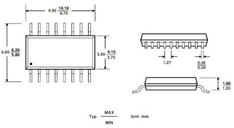
The Hx711 chip comes in a 16-pin SOP-16 package. Here’s a table detailing the pinout configuration:
| Pin Number | Pin Name | Description | Input/Output |
|---|---|---|---|
| 1 | VSUP | Digital and analog supply voltage: 2.6-5.5V | Power |
| 2 | BASE | Regulate output voltage: VSUP-1.25V | Power |
| 3 | AVDD | Analog supply voltage: 2.6-5.5V | Power |
| 4 | VFB | Analog input to the internal ADC | Input |
| 5 | AGND | Analog ground | Power |
| 6 | VBG | Reference bypass output | Output |
| 7 | INA | Channel A positive input | Input |
| 8 | INB | Channel B positive input | Input |
| 9 | RATE | Output data rate control | Input |
| 10 | DOUT/DRDY | Serial data output/data ready | Output |
| 11 | XIN | Crystal or external clock input: 10-15MHz | Input |
| 12 | XOUT | Crystal or external clock output | Output |
| 13 | DVDD | Digital supply voltage | Power |
| 14 | DGND | Digital ground | Power |
| 15 | INNA | Channel A negative input | Input |
| 16 | INNB | Channel B negative input | Input |
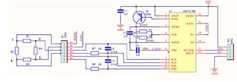
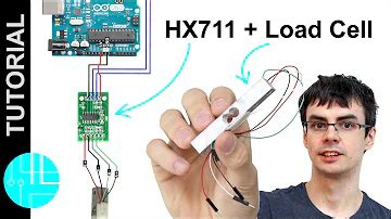
Connecting the Hx711 to a Load Cell
To connect a load cell to the Hx711, you’ll need to identify the load cell’s wire colors and their corresponding functions. A typical load cell has four wires:
- Red: Excitation+
- Black: Excitation-
- White: Signal+
- Green: Signal-
Connect the load cell wires to the Hx711 as follows:
| Load Cell Wire | Hx711 Pin |
|---|---|
| Red (E+) | AVDD |
| Black (E-) | AGND |
| White (S+) | INA |
| Green (S-) | INNA |
Connecting the Hx711 to a Microcontroller
To interface the Hx711 with a microcontroller, you’ll need to connect the following pins:
| Hx711 Pin | Microcontroller Pin |
|---|---|
| VSUP | VCC |
| DVDD | VCC |
| DGND | GND |
| DOUT/DRDY | Digital Input Pin |
| PD_SCK | Digital Output Pin |
The microcontroller communicates with the Hx711 using a simple serial interface. The DOUT/DRDY pin outputs the converted data and indicates when new data is ready, while the PD_SCK pin is used to input serial clock and control data.

Using the Hx711 in Your Project
Now that you understand the Hx711 chip’s pinout and how to connect it to a load cell and microcontroller, let’s discuss how to use it in your project.
Setting the Gain and Input Channel
The Hx711’s PGA has three selectable gain settings: 32, 64, and 128. To set the gain, you’ll need to send the appropriate number of pulses on the PD_SCK pin while the DOUT/DRDY pin is high. The number of pulses corresponds to the desired gain:
- 25 pulses: Gain of 128
- 26 pulses: Gain of 32
- 27 pulses: Gain of 64
You can also select which input channel to use (A or B) by sending the appropriate number of pulses:
- 25 or 26 pulses: Channel A
- 27 pulses: Channel B
Reading Data from the Hx711
To read data from the Hx711, follow these steps:
- Wait for the DOUT/DRDY pin to go low, indicating that data is ready.
- Send 24 clock pulses on the PD_SCK pin to shift out the data.
- The 24-bit data will be clocked out, MSB first, on the falling edges of PD_SCK.
- Send an additional pulse on PD_SCK to set the next conversion mode.
- The DOUT/DRDY pin will go high, indicating that the chip is ready for the next reading.
Here’s a sample code snippet in Arduino C for reading data from the Hx711:
#define DOUT  6
#define CLK  7

void setup() {
  Serial.begin(9600);
  pinMode(DOUT, INPUT);
  pinMode(CLK, OUTPUT);
}

void loop() {
  while (digitalRead(DOUT));

  byte data[3];
  for (int i = 0; i < 3; i++) {
    for (int j = 0; j < 8; j++) {
      digitalWrite(CLK, HIGH);
      data[i] |= digitalRead(DOUT) << (7 - j);
      digitalWrite(CLK, LOW);
    }
  }

  digitalWrite(CLK, HIGH);
  digitalWrite(CLK, LOW);

  long value = ((long)data[2] << 16) | ((long)data[1] << 8) | (long)data[0];
  Serial.println(value);

  delay(100);
}
Calibrating the Load Cell
To accurately measure weight or force with your load cell and Hx711 setup, you’ll need to calibrate the system. Here’s a simple calibration procedure:
- Record the raw Hx711 output value with no weight on the load cell. This is your zero offset.
- Place a known weight on the load cell and record the raw output value.
- Subtract the zero offset from the known weight raw value. This is your reference value.
- Divide the known weight by the reference value to get a calibration factor.
To calculate the actual weight in your project, subtract the zero offset from the raw Hx711 value, then multiply by the calibration factor.

Hx711 Frequently Asked Questions (FAQ)
1. What is the maximum weight capacity of the Hx711?
The Hx711 itself does not have a maximum weight capacity, as it is an ADC designed to work with various load cells. The maximum weight capacity depends on the specific load cell you are using with the Hx711.
2. Can I use the Hx711 with a 3.3V microcontroller?
Yes, the Hx711 is compatible with both 3.3V and 5V microcontrollers. The chip’s digital supply voltage (DVDD) can range from 2.6V to 5.5V.
3. What is the resolution of the Hx711?
The Hx711 has a 24-bit ADC, which provides a theoretical maximum resolution of approximately 16.7 million counts (2^24). However, the actual resolution will depend on factors such as noise, load cell sensitivity, and calibration.
4. How do I interface multiple load cells with one Hx711?
To interface multiple load cells with a single Hx711, you can wire the load cells in parallel. Connect all the Excitation+ wires together, all the Excitation- wires together, all the Signal+ wires together, and all the Signal- wires together. Then, connect the combined Excitation+, Excitation-, Signal+, and Signal- wires to the corresponding pins on the Hx711.
5. Can I use the Hx711 for applications other than weight measurement?
Yes, the Hx711 can be used with any sensor that outputs a small differential voltage, such as pressure sensors, strain gauges, and Wheatstone Bridges. However, you may need to adjust the gain settings and calibration procedure to accommodate your specific sensor.
Conclusion
The Hx711 load cell amplifier is a versatile and low-cost solution for adding weight or force measurement capabilities to your projects. By understanding the chip’s pinout configuration, features, and usage instructions outlined in this article, you can effectively integrate the Hx711 with your load cell and microcontroller.
Remember to consider factors such as gain settings, calibration, and load cell compatibility when designing your Hx711-based system. With proper implementation, the Hx711 can provide precise and reliable measurements for a wide range of applications.

No responses yet