What is a Parallel Circuit?
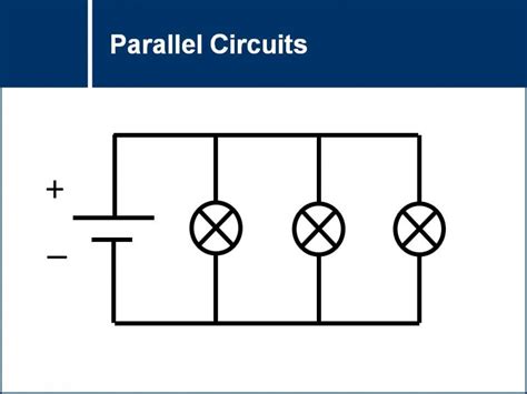
A parallel circuit is an electrical circuit configuration where the components are connected in such a way that the electric current has multiple paths to flow through. In a parallel circuit, the voltage across each component is the same, while the total current is the sum of the currents flowing through each component.
Parallel circuits are commonly used in households and electronic devices because they allow for the independent operation of each component. If one component fails or is removed, the others will continue to function normally.
Characteristics of a Parallel Circuit
| Characteristic | Description |
|---|---|
| Voltage | The voltage across each component is the same as the source voltage. |
| Current | The total current is the sum of the currents flowing through each component. |
| Resistance | The total resistance is less than the resistance of any individual component. |
How Does a Parallel Circuit Work?
In a parallel circuit, the components are connected side by side, forming multiple paths for the electric current to flow. Each component is connected directly to the power source, allowing it to operate independently of the others.
Current Flow in a Parallel Circuit
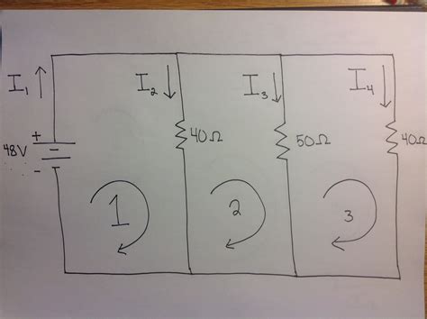
When the power source is connected, the electric current flows through each path simultaneously. The current divides itself among the available paths, with the amount of current in each path being inversely proportional to the resistance of that path.
For example, consider a parallel circuit with two resistors, R1 and R2. The current flowing through each resistor can be calculated using Ohm’s Law:
I1 = V / R1
I2 = V / R2
Where:
– I1 is the current flowing through R1
– I2 is the current flowing through R2
– V is the source voltage
The total current in the circuit is the sum of the currents flowing through each resistor:
Itotal = I1 + I2
Voltage in a Parallel Circuit
In a parallel circuit, the voltage across each component is the same as the source voltage. This is because each component is connected directly to the power source, and there is no voltage drop across any other components in the circuit.
Resistance in a Parallel Circuit
The total resistance in a parallel circuit is always less than the resistance of any individual component. This is because the multiple paths for the current to flow effectively decrease the overall resistance of the circuit.
The formula for calculating the total resistance in a parallel circuit with two resistors is:
1/Rtotal = 1/R1 + 1/R2
For a parallel circuit with more than two resistors, the formula can be extended as follows:
1/Rtotal = 1/R1 + 1/R2 + 1/R3 + … + 1/Rn

Advantages and Disadvantages of Parallel Circuits
Advantages
- Independent operation of components
- If one component fails, the others continue to function
- Easy to add or remove components without affecting the entire circuit
- Lower total resistance compared to series circuits
Disadvantages
- Higher current draw compared to series circuits
- More complex wiring and connections
- Increased risk of short circuits if not properly designed and maintained

Applications of Parallel Circuits
Parallel circuits are widely used in various applications, including:
- Household wiring systems
- Electronic devices (e.g., televisions, computers)
- Automotive electrical systems
- Lighting systems
- Power distribution networks

Designing a Parallel Circuit
When designing a parallel circuit, consider the following factors:
- The voltage and current requirements of each component
- The total current draw of the circuit
- The wire gauge and insulation suitable for the expected current
- Proper fusing and Circuit Protection
- Adequate ventilation and heat dissipation for components
Example: Designing a Simple Parallel Circuit
Let’s design a simple parallel circuit with three LED lights and a 9V battery.
Step 1: Determine the voltage and current requirements
- LED voltage drop: 2V
- LED current: 20mA
- Battery voltage: 9V
Step 2: Calculate the resistor values
Using Ohm’s Law, we can calculate the required resistor value for each LED:
R = (Vbattery – VLED) / ILED
R = (9V – 2V) / 0.02A
R = 350 ohms
We can use standard 330-ohm resistors for each LED.
Step 3: Connect the components
- Connect the positive terminal of the battery to one side of each resistor.
- Connect the other side of each resistor to the positive (anode) of each LED.
- Connect the negative (cathode) of each LED to the negative terminal of the battery.
Step 4: Test the circuit
Connect the battery and verify that all three LEDs illuminate. If any LED does not light up, check the connections and ensure the polarity is correct.
Troubleshooting Parallel Circuits
If a parallel circuit is not functioning correctly, follow these troubleshooting steps:
-
Check the power source: Ensure the battery or power supply is providing the correct voltage and is properly connected.
-
Verify component connections: Check that all components are properly connected and that there are no loose or broken connections.
-
Test individual components: Remove each component from the circuit and test it separately to identify any faulty components.
-
Check for short circuits: Inspect the wiring for any signs of damage or insulation failure that could cause a short circuit.
-
Measure voltage and current: Use a multimeter to measure the voltage across each component and the current flowing through the circuit to identify any anomalies.
Safety Considerations
When working with electrical circuits, always prioritize safety:
- Disconnect power sources before working on the circuit.
- Use appropriate tools and personal protective equipment (e.g., insulated pliers, safety glasses).
- Follow proper wiring techniques and use appropriate wire gauges and insulation.
- Ensure proper fusing and circuit protection to prevent overloading and fire hazards.
- Work in a well-ventilated area and avoid touching exposed conductors.
Frequently Asked Questions (FAQ)
1. What is the difference between a parallel circuit and a series circuit?
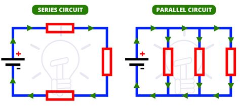
In a parallel circuit, components are connected side by side, allowing the current to flow through multiple paths simultaneously. The voltage across each component is the same, and the total current is the sum of the currents flowing through each path.
In a series circuit, components are connected end to end, forming a single path for the current to flow. The current is the same through each component, and the voltage drops across each component, with the total voltage being the sum of the individual voltage drops.
2. Can I mix different types of components in a parallel circuit?
Yes, you can mix different types of components (e.g., resistors, LEDs, capacitors) in a parallel circuit as long as they are rated for the same voltage and can handle the expected current flowing through them.
3. What happens if one component in a parallel circuit fails?
If one component in a parallel circuit fails or is removed, the other components will continue to function normally. This is because each component is connected directly to the power source and has its own path for the current to flow.
4. How do I calculate the total resistance in a parallel circuit?
The total resistance in a parallel circuit is always less than the resistance of any individual component. The formula for calculating the total resistance is:
1/Rtotal = 1/R1 + 1/R2 + 1/R3 + … + 1/Rn
Where R1, R2, R3, …, Rn are the individual resistances of the components in the circuit.
5. Can I connect batteries in parallel to increase the voltage?
No, connecting batteries in parallel will not increase the voltage. Instead, it will increase the total current capacity of the battery pack. To increase the voltage, you would need to connect the batteries in series.
Conclusion
Parallel circuits are a fundamental concept in Electrical Engineering and are widely used in various applications. By understanding the characteristics, advantages, and disadvantages of parallel circuits, you can effectively design, troubleshoot, and maintain these circuits in your projects.
Remember to prioritize safety when working with electrical circuits and always follow proper wiring techniques and use appropriate tools and protective equipment.
With this comprehensive guide, you should now have a solid foundation in simple parallel circuits and be well-equipped to apply this knowledge in your future electrical projects.

No responses yet