Table of Contents
- Introduction to Infrared Communication
- Components of an Infrared Receiver Circuit
- Working Principle of Infrared Receiver Circuits
- Design Considerations for Infrared Receiver Circuits
- Applications of Infrared Receiver Circuits
- Frequently Asked Questions (FAQ)
- Conclusion
- References
Introduction to Infrared Communication
Infrared communication is a wireless technology that uses infrared light to transmit data between devices. This type of communication is often used for short-range, line-of-sight applications. IR light has a wavelength ranging from 700 nm to 1 mm, which is just beyond the visible light spectrum.
Infrared communication offers several advantages over other wireless technologies:
– Low power consumption
– Low cost
– Immunity to electromagnetic interference
– No need for government licensing or regulation
However, it also has some limitations:
– Short transmission range (typically up to 10 meters)
– Line-of-sight requirement
– Susceptibility to interference from ambient light sources

Components of an Infrared Receiver Circuit
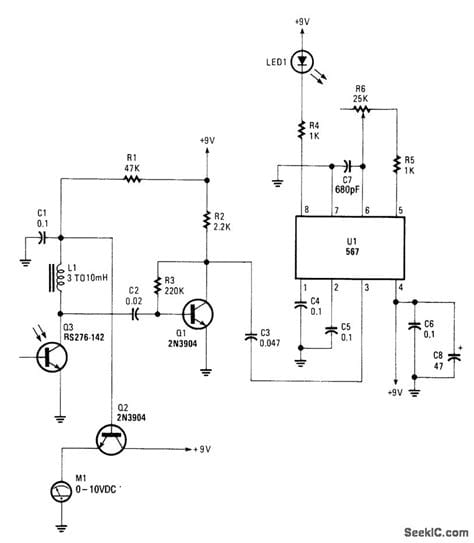
A typical infrared receiver circuit consists of the following key components:
-
Infrared Photodiode: This is the main sensor that detects the incoming IR light. When IR light strikes the photodiode, it generates a small current proportional to the light intensity.
-
Preamplifier: The current generated by the photodiode is very small and needs to be amplified before further processing. The preamplifier, usually an operational amplifier (op-amp), converts the current into a voltage signal and provides initial amplification.
-
Bandpass Filter: The amplified signal may contain noise and interference from other light sources. A bandpass filter is used to remove these unwanted components and allow only the desired IR signal frequencies to pass through.
-
Demodulator: IR communication typically uses Modulation Techniques, such as on-off keying (OOK) or pulse-width modulation (PWM), to encode data. The demodulator extracts the original data from the filtered signal.
-
Microcontroller or Decoder: The demodulated signal is then processed by a microcontroller or a dedicated decoder IC, which decodes the received data and performs the necessary actions based on the application.
| Component | Function |
|---|---|
| IR Photodiode | Detects incoming IR light and generates a small current |
| Preamplifier | Amplifies the photodiode current and converts it to voltage |
| Bandpass Filter | Removes noise and interference from the amplified signal |
| Demodulator | Extracts the original data from the filtered signal |
| Microcontroller/Decoder | Decodes the received data and performs necessary actions |

Working Principle of Infrared Receiver Circuits
The working principle of an infrared receiver circuit can be broken down into the following steps:
-
IR Signal Detection: When an IR signal is transmitted, the IR light pulses strike the photodiode in the receiver circuit. The photodiode converts the light energy into a small electrical current.
-
Current-to-Voltage Conversion and Amplification: The preamplifier, typically an op-amp in a transimpedance configuration, converts the small photodiode current into a voltage signal and provides initial amplification. This step is crucial because the photodiode current is usually in the range of microamperes, which is too small to be processed directly.
-
Noise and Interference Removal: The amplified signal may contain noise and interference from ambient light sources, such as sunlight or artificial lighting. To remove these unwanted components, the signal passes through a bandpass filter. The filter is designed to allow only the desired IR signal frequencies to pass through while attenuating other frequencies.
-
Demodulation: The filtered signal is then demodulated to extract the original data. The most common modulation techniques used in IR communication are on-off keying (OOK) and pulse-width modulation (PWM).
- In OOK, the presence of an IR pulse represents a binary ‘1’, and the absence of a pulse represents a binary ‘0’.
- In PWM, the width of the IR pulse determines the binary value: a short pulse represents a ‘0’, and a long pulse represents a ‘1’.
The demodulator compares the incoming signal with a reference threshold to determine the binary value of each bit.
- Data Processing: The demodulated binary data is sent to a microcontroller or a dedicated decoder IC for further processing. The microcontroller or decoder interprets the received data and performs the necessary actions based on the application. For example, in a remote control system, the microcontroller may decode the received commands and control the corresponding functions of the device.

Design Considerations for Infrared Receiver Circuits
When designing an infrared receiver circuit, several factors must be taken into account to ensure optimal performance and reliability:
-
Photodiode Selection: Choose a photodiode with high sensitivity in the desired IR wavelength range (typically 850 nm to 950 nm). The photodiode should also have a fast response time to accommodate the data rates used in the application.
-
Preamplifier Design: The preamplifier should have a high gain to amplify the small photodiode current effectively. It should also have a low input impedance to minimize the effect of photodiode capacitance, which can limit the bandwidth. A transimpedance amplifier configuration is commonly used, as it converts the photodiode current to a voltage signal while providing a low input impedance.
-
Bandpass Filter Design: The bandpass filter should be designed to match the frequency range of the IR signal. The filter’s center frequency and bandwidth should be chosen based on the modulation scheme and data rate used in the application. A narrow bandwidth will provide better noise rejection but may limit the data rate, while a wider bandwidth allows for higher data rates but may be more susceptible to interference.
-
Demodulator Selection: The choice of demodulator depends on the modulation scheme used. For OOK modulation, a comparator with a suitable reference threshold can be used. For PWM, a more complex demodulator, such as a pulse-width discriminator or a digital decoder, may be required.
-
Microcontroller or Decoder Selection: The microcontroller or decoder should have sufficient processing power and memory to handle the received data and perform the necessary actions. It should also have the appropriate communication interfaces (e.g., UART, I2C, SPI) to interact with other components in the system.
-
Noise and Interference Reduction: To minimize the impact of ambient light interference, use optical filters that block visible light while allowing IR light to pass through. Additionally, proper shielding and grounding techniques should be employed to reduce electromagnetic interference (EMI) and ensure signal integrity.
-
Power Management: Infrared receiver circuits are often used in battery-powered devices, so power consumption is a critical consideration. Use low-power components and implement power-saving techniques, such as sleep modes or wake-on-signal functionality, to prolong battery life.
Applications of Infrared Receiver Circuits
Infrared receiver circuits find applications in a wide range of fields, including:
-
Remote Controls: IR receiver circuits are extensively used in remote controls for televisions, set-top boxes, air conditioners, and other consumer electronics. They enable users to control these devices wirelessly from a distance.
-
Wireless Data Transfer: IR communication can be used for short-range wireless data transfer between devices, such as computers, smartphones, and peripherals. This application is less common today due to the prevalence of radio frequency (RF) technologies like Bluetooth and Wi-Fi.
-
Proximity Sensing: IR receiver circuits can detect the presence or absence of objects by measuring the reflection of IR light. This principle is used in various applications, such as automatic doors, touchless faucets, and obstacle detection in robotics.
-
Infrared Thermometers: Non-contact infrared thermometers use IR receiver circuits to measure the temperature of objects from a distance. These devices detect the IR radiation emitted by the object and convert it into a temperature reading.
-
Industrial Automation: IR communication is used in industrial automation systems for wireless data transmission between sensors, controllers, and actuators. It provides a reliable and cost-effective solution for short-range communication in harsh industrial environments.
-
Medical Devices: IR receiver circuits are used in medical devices, such as pulse oximeters, which measure the oxygen saturation in a patient’s blood. The receiver circuit detects the IR light transmitted through the patient’s finger and calculates the oxygen levels based on the absorption characteristics of hemoglobin.
-
Automotive Applications: IR receiver circuits are employed in various automotive applications, such as keyless entry systems, tire pressure monitoring systems (TPMS), and in-cabin temperature sensing.
Frequently Asked Questions (FAQ)
-
What is the typical range of infrared communication?
Infrared communication typically has a range of up to 10 meters, depending on the power of the transmitter and the sensitivity of the receiver. However, in most consumer applications, such as remote controls, the practical range is usually around 5-7 meters. -
Can infrared communication work through walls or obstacles?
No, infrared communication requires a clear line-of-sight between the transmitter and the receiver. IR light cannot penetrate walls or other opaque obstacles, which is why remote controls need to be pointed directly at the device they are controlling. -
What are the advantages of infrared communication over radio frequency (RF) communication?
Infrared communication has several advantages over RF communication: - Lower power consumption
- Lower cost of implementation
- No interference with other RF devices
-
No need for government licensing or regulation
-
How does ambient light affect infrared receiver circuits?
Ambient light, such as sunlight or artificial lighting, can interfere with infrared receiver circuits. This is because the photodiode in the receiver circuit is sensitive to a wide range of light frequencies, including visible light. To mitigate this issue, optical filters are used to block visible light while allowing IR light to pass through. Additionally, proper circuit design and noise reduction techniques help minimize the impact of ambient light interference. -
What are the common modulation techniques used in infrared communication?
The two most common modulation techniques used in infrared communication are: - On-Off Keying (OOK): In this technique, the presence of an IR pulse represents a binary ‘1’, and the absence of a pulse represents a binary ‘0’.
- Pulse-Width Modulation (PWM): In PWM, the width of the IR pulse determines the binary value: a short pulse represents a ‘0’, and a long pulse represents a ‘1’.
Conclusion
Infrared receiver circuits play a crucial role in enabling wireless communication using IR light. By understanding the design, working principle, and applications of these circuits, engineers and enthusiasts can develop efficient and reliable IR communication systems. When designing an infrared receiver circuit, careful consideration must be given to component selection, noise reduction, and power management to ensure optimal performance.
As technology continues to evolve, infrared communication may find new applications in emerging fields, such as the Internet of Things (IoT) and wearable devices. By leveraging the advantages of IR communication, designers can create innovative solutions that are cost-effective, energy-efficient, and secure.
References
- Kesler, M. (2017). Infrared Receiver Design for Data Communication. Analog Devices.
- Saha, S., & Majumdar, A. (2019). A Comprehensive Study on Infrared Wireless Communication. IETE Technical Review, 36(1), 1-11.
- Horowitz, P., & Hill, W. (2015). The Art of Electronics (3rd ed.). Cambridge University Press.
- Hagerty, J. A., & Zhao, F. (2006). Infrared Wireless Data Communication. In J. D. Gibson (Ed.), Mobile Communications Handbook (3rd ed., pp. 1-15). CRC Press.
- Kafi, M. A., Rahman, M. M., & Islam, M. R. (2018). Infrared Receiver Circuit Design and Application. In Optical and Wireless Technologies (pp. 461-469). Springer, Singapore.

No responses yet