Introduction to PCB Layout Design
Printed Circuit Board (PCB) layout design is a crucial step in the development of electronic devices. It involves the arrangement of components and the routing of electrical connections on a PCB to ensure optimal performance, reliability, and manufacturability. In this comprehensive article, we will explore the fundamentals of PCB layout design, best practices, and tips to help you create robust and efficient PCB layouts.
Understanding the Basics of PCB Layout
What is a PCB?
A PCB is a flat board made of insulating material, such as fiberglass or plastic, with conductive copper traces etched onto its surface. It serves as a foundation for mounting and interconnecting electronic components, such as resistors, capacitors, integrated circuits (ICs), and connectors.
Layers in a PCB
PCBs can have multiple layers, depending on the complexity of the design and the required functionality. The most common PCB layer configurations are:
| Layers | Description |
|---|---|
| Single-layer | A PCB with conductive traces on only one side of the board. |
| Double-layer | A PCB with conductive traces on both sides of the board. |
| Multi-layer | A PCB with conductive traces on multiple layers, separated by insulating material. |
Components in a PCB Layout
A PCB layout consists of various components, each serving a specific purpose. Some of the essential components include:
- Pads: Conductive areas where components are soldered to the PCB.
- Traces: Conductive paths that connect components and carry electrical signals.
- Vias: Conductive holes that allow traces to pass through different layers of the PCB.
- Solder Mask: A protective coating applied to the PCB to prevent short circuits and protect the copper traces from oxidation.
- Silkscreen: Text and symbols printed on the PCB for component identification and assembly instructions.
PCB Layout Design Process
Schematic Design
The first step in the PCB layout design process is creating a schematic diagram. A schematic represents the logical connections between components and helps define the functionality of the circuit. It is essential to ensure that the schematic is accurate and complete before proceeding to the layout stage.
Component Placement
Once the schematic is finalized, the next step is to place the components on the PCB. Proper component placement is crucial for several reasons:
- Signal Integrity: Components should be placed to minimize the length of critical signal paths and reduce crosstalk.
- Thermal Management: Components that generate significant heat should be placed in a way that allows for adequate cooling.
- Mechanical Constraints: Component placement should consider the physical dimensions of the PCB and any mechanical constraints, such as connectors or mounting holes.
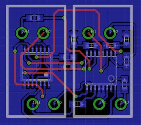
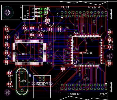
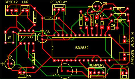
Routing
After component placement, the traces that connect the components must be routed. Routing is the process of creating conductive paths between pads and vias while adhering to design rules and constraints. Some important considerations during routing include:
- Trace Width: The width of the traces should be appropriate for the current carrying capacity and the manufacturing capabilities.
- Spacing: Adequate spacing between traces and components is necessary to prevent short circuits and ensure manufacturability.
- Signal Integrity: Critical signals, such as high-speed or sensitive analog signals, may require special routing techniques, such as controlled impedance or Differential pairs.
Ground and Power Planes
In multi-layer PCBs, dedicated layers are often used for ground and power distribution. These layers, known as planes, provide a low-impedance path for return currents and help reduce electromagnetic interference (EMI). Proper design of ground and power planes is essential for maintaining signal integrity and minimizing noise.

Best Practices for PCB Layout Design
To ensure a reliable and manufacturable PCB layout, consider the following best practices:
-
Keep It Simple: Strive for a clean and simple layout that is easy to understand and manufacture.
-
Minimize Trace Length: Keep traces as short as possible to reduce signal degradation and improve signal integrity.
-
Avoid Sharp Angles: Use 45-degree angles or curved traces instead of 90-degree angles to reduce signal reflections and improve manufacturability.
-
Provide Adequate Clearances: Maintain sufficient clearance between components, traces, and board edges to prevent short circuits and ensure reliable operation.
-
Consider Manufacturability: Design your PCB layout with manufacturing constraints in mind, such as minimum trace width, spacing, and hole sizes.
-
Use Proper Grounding Techniques: Implement a solid grounding strategy, such as a ground plane or a star ground, to minimize noise and ensure stable operation.
-
Optimize for Signal Integrity: Pay attention to signal integrity issues, such as crosstalk, Impedance Matching, and termination, especially for high-speed designs.
-
Perform Design Rule Checks (DRC): Use DRC tools provided by PCB design software to verify that your layout adheres to the specified design rules and constraints.
Common PCB Layout Design Challenges and Solutions
Crosstalk
Crosstalk occurs when signals from one trace interfere with signals on a nearby trace. To mitigate crosstalk:
- Increase the spacing between sensitive traces
- Use guard traces or ground planes to isolate sensitive signals
- Route critical traces on different layers
Electromagnetic Interference (EMI)
EMI can cause unwanted noise and disrupt the operation of electronic devices. To reduce EMI:
- Use proper grounding and shielding techniques
- Minimize loop areas and trace lengths
- Implement filtering and decoupling capacitors
Thermal Management
Overheating can lead to component failure and decreased reliability. To improve thermal management:
- Place heat-generating components in areas with good airflow
- Use thermal vias to transfer heat to other layers or planes
- Consider using heat sinks or thermal pads for high-power components
Manufacturing Constraints
PCB layout design must consider the limitations and capabilities of the manufacturing process. To ensure manufacturability:
- Adhere to the minimum trace width and spacing specified by the manufacturer
- Use standard hole sizes and pad dimensions
- Provide sufficient clearance for tooling and assembly
PCB Layout Design Tools
There are various PCB layout design tools available, ranging from free and open-source software to professional-grade commercial solutions. Some popular PCB layout design tools include:
- KiCad
- Eagle
- Altium Designer
- OrCAD
- Mentor Graphics PADS
When choosing a PCB layout design tool, consider factors such as ease of use, feature set, compatibility with other tools, and cost.
Frequently Asked Questions (FAQ)
- What is the difference between a schematic and a PCB layout?
-
A schematic represents the logical connections between components, while a PCB layout shows the physical arrangement of components and traces on a PCB.
-
How do I determine the appropriate trace width for my PCB layout?
-
Trace width depends on factors such as the current carrying capacity, the thickness of the copper layer, and the manufacturing capabilities. Consult the manufacturer’s guidelines or use online trace width calculators for guidance.
-
What is the purpose of a solder mask in a PCB layout?
-
A solder mask is a protective coating applied to the PCB that prevents short circuits and protects the copper traces from oxidation and damage during soldering.
-
How can I minimize crosstalk in my PCB layout?
-
To minimize crosstalk, increase the spacing between sensitive traces, use guard traces or ground planes to isolate signals, and route critical traces on different layers.
-
What are the benefits of using a ground plane in a PCB layout?
- A ground plane provides a low-impedance path for return currents, helps reduce electromagnetic interference (EMI), and improves signal integrity by minimizing noise and ensuring stable operation.
Conclusion
Designing a PCB layout is a complex process that requires careful consideration of various factors, such as component placement, routing, signal integrity, and manufacturability. By understanding the fundamentals of PCB layout design, following best practices, and using the right tools, you can create robust and efficient PCB layouts that meet your design requirements and ensure reliable operation of your electronic devices.
No responses yet