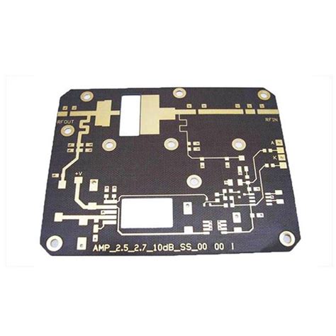
Introduction to Microwave PCB
Microwave PCBs, or printed circuit boards designed for high-frequency applications, play a crucial role in modern electronic systems. These specialized PCBs are used in various industries, including telecommunications, aerospace, defense, and consumer electronics. The successful fabrication of microwave PCBs requires careful consideration of materials, design techniques, and manufacturing processes to ensure optimal performance and reliability.
In this article, we will discuss essential tips for achieving successful microwave PCB fabrication, covering key aspects such as material selection, design guidelines, manufacturing processes, and testing procedures.
Importance of Material Selection
Substrate Materials
The choice of substrate material is critical in microwave PCB fabrication. The substrate must have the appropriate dielectric constant (Dk) and dissipation factor (Df) to minimize signal loss and distortion at high frequencies. Some commonly used substrate materials for microwave PCBs include:
| Material | Dielectric Constant (Dk) | Dissipation Factor (Df) |
|---|---|---|
| Rogers RO4003C | 3.38 | 0.0027 |
| Rogers RT/duroid 5880 | 2.20 | 0.0009 |
| Isola I-Tera MT40 | 3.45 | 0.0031 |
| Taconic RF-35 | 3.50 | 0.0018 |
Copper Foil
The copper foil used in microwave PCBs should have a low surface roughness to minimize skin effect losses at high frequencies. Electrodeposited (ED) copper foil is preferred over rolled copper foil due to its smoother surface finish. The thickness of the copper foil should also be carefully selected based on the desired trace width and impedance requirements.

Design Guidelines for Microwave PCBs
Controlled Impedance
Maintaining controlled impedance throughout the PCB is essential for minimizing signal reflections and ensuring proper signal integrity. The impedance of microwave traces is determined by factors such as trace width, substrate thickness, and dielectric constant. Designers should use impedance calculators or simulation tools to determine the appropriate trace dimensions for the desired impedance.
Grounding and Shielding
Proper grounding and shielding techniques are crucial in microwave PCB design to minimize electromagnetic interference (EMI) and crosstalk between signals. Some key considerations include:
- Using a solid ground plane to provide a low-impedance return path for high-frequency signals
- Implementing via fencing or guard traces to isolate sensitive signals
- Incorporating shielding enclosures or cavities to contain electromagnetic fields
Component Placement and Routing
The placement and routing of components on a microwave PCB should be optimized to minimize signal path lengths and avoid unnecessary discontinuities. Some guidelines to follow include:
- Place components as close to their associated traces as possible
- Avoid sharp bends or corners in traces to minimize reflections
- Use smooth, tapered transitions when changing trace widths or connecting to components

Manufacturing Processes for Microwave PCBs
Multilayer Fabrication
Microwave PCBs often require multilayer fabrication to accommodate complex circuitry and provide adequate shielding. The fabrication process involves laminating multiple layers of substrate material with patterned copper foil and bonding them together under heat and pressure. Strict process control is necessary to ensure proper layer registration and avoid defects such as delamination or voids.
Via Formation
Vias play a critical role in interconnecting different layers of a multilayer microwave PCB. The via formation process should be carefully controlled to ensure proper via geometry and minimize signal loss. Some common via formation techniques include:
- Mechanical drilling followed by electroplating
- Laser drilling for smaller via sizes
- Conductive paste filling for high-aspect-ratio vias
Surface Finishes
The choice of surface finish for a microwave PCB can impact its performance and reliability. Some commonly used surface finishes include:
- Immersion gold (ENIG) for improved solderability and corrosion resistance
- Immersion silver (IAg) for lower cost and compatibility with aluminum wire bonding
- Electroless nickel electroless palladium immersion gold (ENEPIG) for enhanced durability and wire bonding capabilities

Testing and Validation
S-Parameter Measurements
Scattering parameters, or S-parameters, are used to characterize the performance of microwave PCBs and components. S-parameter measurements are typically performed using a vector network analyzer (VNA) to evaluate characteristics such as insertion loss, return loss, and crosstalk. These measurements help validate the design and ensure compliance with specifications.
Time-Domain Reflectometry (TDR)
Time-domain reflectometry (TDR) is a technique used to identify and locate impedance discontinuities in microwave PCBs. TDR measurements involve sending a fast-rising pulse through the PCB and analyzing the reflected waveform to detect impedance mismatches. This technique is particularly useful for optimizing via transitions and identifying manufacturing defects.
Thermal Management
Microwave PCBs often dissipate significant amounts of power, which can lead to thermal management challenges. Adequate thermal management is necessary to ensure reliable operation and prevent component failure. Some strategies for thermal management in microwave PCBs include:
- Using high-thermal-conductivity substrates such as aluminum nitride (AlN) or beryllium oxide (BeO)
- Incorporating thermal vias or heat sinks to dissipate heat away from components
- Employing active cooling techniques such as forced air or liquid cooling for high-power applications
Frequently Asked Questions (FAQ)
1. What is the difference between microwave PCBs and regular PCBs?
Microwave PCBs are designed specifically for high-frequency applications, typically operating at frequencies above 1 GHz. They require specialized materials, design techniques, and manufacturing processes to ensure optimal performance and signal integrity at these high frequencies. Regular PCBs, on the other hand, are designed for lower frequency applications and may not have the same stringent requirements for materials and manufacturing processes.
2. Why is the choice of substrate material important for microwave PCBs?
The choice of substrate material is critical for microwave PCBs because it directly impacts the signal integrity and performance at high frequencies. The substrate must have the appropriate dielectric constant (Dk) and dissipation factor (Df) to minimize signal loss and distortion. Materials with low Dk and Df values, such as Rogers RO4003C or RT/duroid 5880, are commonly used in microwave PCBs to achieve optimal performance.
3. What are some common design challenges in microwave PCB layout?
Some common design challenges in microwave PCB layout include maintaining controlled impedance, minimizing signal reflections and crosstalk, and ensuring proper grounding and shielding. Designers must carefully consider factors such as trace dimensions, component placement, and routing to optimize signal integrity and minimize electromagnetic interference (EMI).
4. How do vias impact the performance of microwave PCBs?
Vias play a crucial role in interconnecting different layers of a multilayer microwave PCB. However, vias can also introduce impedance discontinuities and signal loss if not designed and manufactured properly. The via geometry, including diameter, pitch, and plating thickness, must be carefully controlled to minimize signal degradation. Techniques such as via fencing, backdrilling, and conductive paste filling can be used to optimize via performance in microwave PCBs.
5. What are some common testing methods for microwave PCBs?
Common testing methods for microwave PCBs include S-parameter measurements using a vector network analyzer (VNA) and time-domain reflectometry (TDR). S-parameter measurements help characterize the performance of the PCB and components, evaluating characteristics such as insertion loss, return loss, and crosstalk. TDR measurements are used to identify and locate impedance discontinuities in the PCB, which is particularly useful for optimizing via transitions and identifying manufacturing defects.
Conclusion
Successful microwave PCB fabrication requires careful consideration of materials, design techniques, manufacturing processes, and testing procedures. By selecting the appropriate substrate materials, following design guidelines for controlled impedance and shielding, and employing specialized manufacturing processes, designers can ensure optimal performance and reliability of their microwave PCBs.
Thorough testing and validation, including S-parameter measurements and time-domain reflectometry, are essential for identifying and addressing any performance issues before the PCBs are integrated into the final application.
By adhering to these essential tips and best practices, designers and manufacturers can achieve successful microwave PCB fabrication and deliver high-quality, reliable products for a wide range of high-frequency applications.
No responses yet