Understanding the Basics of RF PCB Design
What is RF PCB Design?
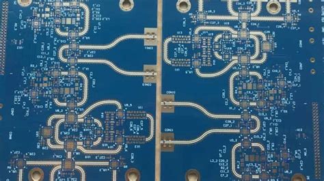
RF PCB design involves the creation of printed circuit boards that operate at high frequencies, typically in the range of 100 MHz to 100 GHz. These PCBs are used in various applications, such as wireless communication systems, radar, and satellite technology. The primary goal of RF PCB design is to minimize signal loss, maintain signal integrity, and optimize the overall performance of the circuit.
Key Challenges in RF PCB Design
Designing RF PCBs presents several unique challenges compared to traditional low-frequency PCB design:
-
Signal Integrity: At high frequencies, signal integrity becomes a critical concern. Factors such as impedance matching, reflections, and crosstalk can significantly impact the performance of the circuit.
-
Electromagnetic Interference (EMI): RF circuits are susceptible to EMI, which can cause unwanted noise and interference. Proper shielding and grounding techniques are essential to minimize EMI.
-
Parasitic Effects: Parasitic capacitance and inductance become more prominent at high frequencies, affecting the circuit’s behavior and potentially causing instability or oscillations.
-
Material Selection: The choice of PCB substrate material is crucial for RF designs, as it influences the dielectric constant, loss tangent, and thermal properties of the board.
Choosing the Right PCB Material for RF Design
Common PCB Materials for RF Applications
Several PCB materials are commonly used in RF and microwave designs:
| Material | Dielectric Constant | Loss Tangent | Thermal Conductivity (W/mK) |
|---|---|---|---|
| FR-4 | 4.3 – 4.7 | 0.02 – 0.03 | 0.3 – 0.4 |
| Rogers RO4003C | 3.38 | 0.0027 | 0.71 |
| Rogers RO4350B | 3.48 | 0.0037 | 0.62 |
| PTFE (Teflon) | 2.1 | 0.0002 | 0.25 |
| Alumina (Ceramic) | 9.8 | 0.0001 | 30 |
When selecting a PCB material for RF design, consider the following factors:
-
Dielectric Constant: A lower dielectric constant reduces the capacitance between traces and minimizes signal propagation delay.
-
Loss Tangent: A lower loss tangent minimizes the dielectric losses and improves signal integrity at high frequencies.
-
Thermal Conductivity: Higher thermal conductivity helps dissipate heat generated by components and prevents excessive temperature rise.
-
Cost and Availability: Some high-performance RF materials can be expensive and have longer lead times compared to standard PCB materials like FR-4.

Component Placement and Layout Considerations
General Guidelines for Component Placement
-
Place components as close to each other as possible to minimize trace lengths and reduce signal losses.
-
Arrange components in a logical flow, following the signal path from input to output.
-
Keep sensitive components, such as amplifiers and filters, away from noisy components like power supplies and digital circuits.
-
Use symmetry in component placement to maintain signal balance and reduce unwanted coupling.
Routing Techniques for RF PCBs
-
Microstrip: Microstrip is a popular routing technique for RF PCBs, where the signal trace is placed on the top layer, and a ground plane is located on the bottom layer. The trace width and substrate thickness determine the characteristic impedance of the microstrip.
-
Stripline: Stripline routing involves placing the signal trace between two ground planes, providing better shielding and reduced radiation compared to microstrip. However, stripline requires more layers and can be more challenging to fabricate.
-
Coplanar Waveguide (CPW): CPW consists of a signal trace with ground planes on either side, all on the same layer. This technique offers good isolation and is suitable for high-frequency designs.
-
Grounded Coplanar Waveguide (GCPW): GCPW is similar to CPW but includes an additional ground plane on the bottom layer, providing better shielding and reduced dispersion.
Impedance Matching and Termination
Impedance matching is crucial in RF PCB design to minimize reflections and ensure maximum power transfer. Some common techniques for impedance matching include:
-
Series and Parallel Matching: Using discrete components like capacitors and inductors to match the impedance of the source to the load.
-
Stub Matching: Employing open or short stubs of transmission lines to achieve impedance matching.
-
Tapered Transmission Lines: Gradually changing the width of the transmission line to match the impedance between two different sections.
Proper termination is also essential to prevent reflections and maintain signal integrity. Common termination techniques include:
-
Resistive Termination: Using a resistor equal to the characteristic impedance of the transmission line to absorb reflections.
-
AC-Coupled Termination: Combining a resistor and a capacitor to provide a high-frequency termination while blocking DC bias.

Best Practices for RF PCB Layout
-
Keep trace lengths as short as possible to minimize losses and phase shifts.
-
Avoid sharp bends and corners in traces, as they can cause reflections and impedance mismatches. Use smooth curves or 45-degree angles instead.
-
Maintain consistent trace width and spacing to ensure uniform impedance throughout the signal path.
-
Use ground planes and proper grounding techniques to provide a low-impedance return path and reduce EMI.
-
Implement proper shielding, such as via fences or metal enclosures, to isolate sensitive circuits from interference.
-
Consider the use of RF-specific components, such as RF connectors, RF switches, and RF transformers, to optimize performance.
-
Perform thorough simulations and analysis to validate the design before fabrication, using tools like electromagnetic simulators and circuit simulators.

Frequently Asked Questions (FAQ)
-
Q: What is the difference between RF PCB design and regular PCB design?
A: RF PCB design focuses on high-frequency circuits and requires special considerations for signal integrity, impedance matching, and electromagnetic compatibility. Regular PCB design typically deals with lower frequencies and has less stringent requirements. -
Q: Can I use standard FR-4 material for RF PCB design?
A: While FR-4 can be used for some RF applications, it has limitations due to its higher dielectric constant and loss tangent compared to specialized RF materials like Rogers laminates. FR-4 is more suitable for lower-frequency RF designs or less demanding applications. -
Q: What is the importance of impedance matching in RF PCB design?
A: Impedance matching is crucial in RF PCB design to ensure maximum power transfer, minimize reflections, and maintain signal integrity. Mismatched impedances can lead to signal distortion, reduced efficiency, and potential damage to components. -
Q: How can I reduce electromagnetic interference (EMI) in my RF PCB design?
A: To reduce EMI in RF PCB design, you can use proper shielding techniques (e.g., via fences, metal enclosures), maintain a solid ground plane, keep sensitive traces away from noisy components, and follow good layout practices like minimizing loop areas and using bypass capacitors. -
Q: What are some common simulation tools used for RF PCB design?
A: Some common simulation tools used for RF PCB design include electromagnetic simulators like Ansys HFSS, Keysight ADS, and CST Studio Suite, as well as circuit simulators like LTspice and Keysight ADS. These tools help analyze and optimize the performance of RF circuits before fabrication.
Conclusion
RF PCB design and layout require careful consideration of various factors, including material selection, component placement, routing techniques, and best practices for signal integrity and electromagnetic compatibility. By understanding the unique challenges of RF design, choosing the right PCB materials, implementing proper layout techniques, and following best practices, designers can create high-performance RF and microwave circuits that meet the demanding requirements of modern applications.
No responses yet