Introduction to 555 Timer Delay
The 555 timer is a versatile and widely used integrated circuit (IC) that has been a staple in electronic projects for decades. It is known for its ability to generate precise time delays, pulse generation, and oscillation. In this article, we will explore the 555 timer delay circuit, its components, and various applications. Whether you are a beginner or an experienced electronics enthusiast, understanding the 555 timer delay will open up a world of possibilities for your DIY projects.
How the 555 Timer Delay Works
Basic Principles
The 555 timer IC consists of two comparators, a flip-flop, and an output stage. It has eight pins, each serving a specific function:
- Ground (GND)
- Trigger (TRIG)
- Output (OUT)
- Reset (RESET)
- Control Voltage (CTRL)
- Threshold (THRES)
- Discharge (DISCH)
- Power Supply (VCC)
The 555 timer can operate in two modes: monostable (one-shot) and astable (oscillator). In the monostable mode, the 555 timer generates a single pulse of a specified duration when triggered. In the astable mode, it continuously generates a series of pulses at a determined frequency.
Monostable Mode
In the monostable mode, the 555 timer produces a single output pulse when the trigger pin (TRIG) is momentarily pulled below 1/3 of the supply voltage (VCC). The duration of the output pulse is determined by the values of the external resistor (R) and capacitor (C) connected to the timer.
The pulse duration (t) can be calculated using the following formula:
t = 1.1 × R × C
Where:
– t is the pulse duration in seconds
– R is the resistance in ohms (Ω)
– C is the capacitance in farads (F)
Astable Mode
In the astable mode, the 555 timer continuously generates a series of pulses at a specified frequency. The frequency and duty cycle of the pulses are determined by the values of two external resistors (R1 and R2) and a capacitor (C) connected to the timer.
The frequency (f) and duty cycle (D) can be calculated using the following formulas:
f = 1.44 / ((R1 + 2R2) × C)
D = (R1 + R2) / (R1 + 2R2)
Where:
– f is the frequency in hertz (Hz)
– D is the duty cycle (ratio of pulse width to total cycle time)
– R1 and R2 are resistances in ohms (Ω)
– C is the capacitance in farads (F)

Components Required for 555 Timer Delay Circuit
To build a 555 timer delay circuit, you will need the following components:
- 555 timer IC
- Resistors (values depend on desired delay or frequency)
- Capacitor (value depends on desired delay or frequency)
- Power supply (typically 5V to 15V)
- Breadboard or PCB for prototyping
- Jumper wires
- LED (optional, for visual indication)

Building the 555 Timer Delay Circuit
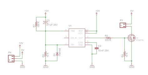
Step 1: Understanding the Schematic
Before building the circuit, it is essential to understand the schematic diagram. The schematic represents the connections between the components and the 555 timer IC. Here’s a simple schematic for a 555 timer delay circuit in monostable mode:
           VCC
            |
            |
            |
            R
            |
            |
TRIG --|--| |--| |-- THRES
      |         |
      |         |
      C         |
      |         |
     GND       GND
Step 2: Gathering Components
Collect all the necessary components based on the schematic and the desired delay or frequency. Make sure to have the correct values for the resistors and capacitor.
Step 3: Assembling the Circuit
- Begin by placing the 555 timer IC on the breadboard or PCB.
- Connect the power supply (VCC) to pin 8 of the 555 timer and ground (GND) to pin 1.
- Connect the resistor (R) between pin 7 (DISCH) and pin 6 (THRES) of the 555 timer.
- Connect the capacitor (C) between pin 2 (TRIG) and ground (GND).
- Connect pin 4 (RESET) to the power supply (VCC) to enable the timer.
- If desired, connect an LED between pin 3 (OUT) and ground (GND) through a current-limiting resistor to visualize the output pulse.
Step 4: Testing the Circuit
- Apply power to the circuit by connecting the power supply to the appropriate pins.
- Trigger the 555 timer by momentarily pulling pin 2 (TRIG) to ground. This can be done using a pushbutton or by manually connecting it to ground.
- Observe the output pulse at pin 3 (OUT). The duration of the pulse will be determined by the values of the resistor (R) and capacitor (C).
- If an LED is connected, it should illuminate for the duration of the output pulse.

Applications of 555 Timer Delay
The 555 timer delay has numerous applications in electronic projects. Here are a few examples:
-
Time-lapse Photography: Use the 555 timer to trigger a camera at regular intervals for capturing time-lapse sequences.
-
Delayed Activation: Create circuits that activate a device or system after a specified time delay, such as turning on lights or starting a motor.
-
Pulse Generation: Generate precise pulses for controlling stepper motors, servos, or other devices that require specific timing.
-
Alarm Systems: Build alarm circuits that sound an alarm after a certain time delay when triggered.
-
Timing Games: Create fun and interactive timing games using the 555 timer, such as reaction time testers or countdown timers.
-
Flashing Lights: Design attention-grabbing flashing light circuits for visual indicators or decorative purposes.
-
Pulse Width Modulation (PWM): Use the 555 timer to generate PWM signals for controlling the brightness of LEDs or the speed of motors.
Troubleshooting and Tips
-
Double-check Connections: Ensure that all components are correctly connected according to the schematic. Incorrect connections can prevent the circuit from functioning properly.
-
Verify Component Values: Make sure that the resistors and capacitor have the correct values for achieving the desired delay or frequency. Incorrect values can result in unexpected behavior.
-
Use Appropriate Power Supply: The 555 timer typically operates between 5V and 15V. Provide a stable and regulated power supply within this range to ensure reliable operation.
-
Consider Debouncing: When using mechanical switches or pushbuttons to trigger the 555 timer, consider implementing debouncing techniques to avoid false triggers caused by switch bounce.
-
Experiment and Optimize: Don’t be afraid to experiment with different component values and configurations to achieve the desired functionality. Optimize your circuit based on your specific requirements.
Frequently Asked Questions (FAQ)
-
Q: What is the purpose of the control voltage (CTRL) pin on the 555 timer?
A: The control voltage pin allows you to modify the threshold voltage levels of the comparators inside the 555 timer. By applying an external voltage to this pin, you can adjust the timing characteristics of the circuit. -
Q: Can I use a potentiometer instead of fixed resistors to adjust the delay or frequency?
A: Yes, you can replace the fixed resistors with a potentiometer to make the delay or frequency adjustable. Connect the potentiometer in series with a fixed resistor to set the minimum and maximum values. -
Q: How do I calculate the values of resistors and capacitor for a specific delay or frequency?
A: Use the formulas provided in the “How the 555 Timer Delay Works” section to calculate the values based on your desired delay or frequency. Rearrange the formulas to solve for the unknown component values. -
Q: Can I cascade multiple 555 timer delay circuits to achieve longer delays?
A: Yes, you can connect multiple 555 timer delay circuits in series to create longer delays. The output of one timer triggers the input of the next timer, resulting in a cumulative delay. -
Q: Are there any limitations to the maximum delay or frequency achievable with the 555 timer?
A: The maximum delay or frequency is limited by the practical values of the resistors and capacitor. Extremely large resistor values or capacitor values may introduce inaccuracies and stability issues. It’s recommended to stay within reasonable component value ranges.
Conclusion
The 555 timer delay is a fundamental building block in electronics that offers a wide range of possibilities for DIY projects. By understanding its working principles, components, and applications, you can create exciting and practical circuits that involve precise timing and control.
Remember to experiment, explore, and have fun while working with the 555 timer delay. With creativity and imagination, you can develop innovative projects that showcase the versatility of this iconic integrated circuit.
Happy tinkering!
| Component | Value Range | Purpose |
|---|---|---|
| Resistor (R) | 1 kΩ to 10 MΩ | Determines the delay or frequency |
| Capacitor (C) | 10 pF to 1000 µF | Determines the delay or frequency |
| Power Supply (VCC) | 5V to 15V | Provides power to the 555 timer |
No responses yet