Introduction to BJT Differential Amplifiers
A BJT (Bipolar Junction Transistor) differential amplifier is a type of electronic amplifier circuit that uses two identical BJTs to amplify the difference between two input signals while rejecting any common-mode signals. This makes them ideal for use in applications where noise reduction and signal integrity are important, such as in audio systems, instrumentation, and communication devices.
Key Characteristics of BJT Differential Amplifiers
- High input impedance
- Low output impedance
- Good common-mode rejection ratio (CMRR)
- Wide bandwidth
- Low noise
How BJT Differential Amplifiers Work
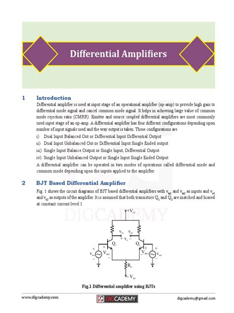
A basic BJT differential amplifier consists of two matched BJTs (Q1 and Q2) with their emitters connected together and biased by a constant current source (IE). The input signals (Vin1 and Vin2) are applied to the bases of Q1 and Q2, respectively. The collectors of Q1 and Q2 are connected to a pair of load resistors (RC1 and RC2), which convert the collector currents into output voltages (Vout1 and Vout2).
Differential Mode Operation
When the input signals Vin1 and Vin2 are different, the BJT differential amplifier operates in differential mode. In this mode, the difference between the input signals causes a difference in the collector currents of Q1 and Q2, which in turn causes a difference in the output voltages Vout1 and Vout2. The differential gain (Ad) of the amplifier is given by:
Ad = (Vout1 – Vout2) / (Vin1 – Vin2)
Common Mode Operation
When the input signals Vin1 and Vin2 are the same (common-mode signal), the BJT differential amplifier ideally produces no output signal. In practice, however, there is always some small output signal due to mismatches between the two BJTs and other circuit components. The ability of the amplifier to reject common-mode signals is measured by the common-mode rejection ratio (CMRR), which is defined as:
CMRR = |Ad| / |Acm|
where Acm is the common-mode gain of the amplifier.

BJT Differential Amplifier Circuit Analysis
To analyze the behavior of a BJT differential amplifier, we can use the small-signal hybrid-π model for the BJTs and apply Kirchhoff’s current and voltage laws (KCL and KVL) to the circuit.
Small-Signal Hybrid-π Model
The small-signal hybrid-π model represents a BJT as a current-controlled current source (gmVπ) in parallel with an input resistance (rπ) and an output resistance (ro). The transconductance (gm) and the base-emitter resistance (rπ) are given by:
gm = IC / VT
rπ = β / gm
where IC is the collector current, VT is the thermal voltage (≈ 26 mV at room temperature), and β is the BJT’s current gain.
KCL and KVL Analysis
Applying KCL at the emitter node:
IE = IC1 + IC2
Applying KVL to the input loop:
Vin1 – Vπ1 – IE(RE) – Vin2 + Vπ2 = 0
Applying KVL to the output loop:
VCC – IC1(RC1) – Vout1 – IE(RE) – Vout2 + IC2(RC2) = 0
Using these equations and the hybrid-π model, we can derive expressions for the differential gain, common-mode gain, and CMRR of the BJT differential amplifier.

BJT Differential Amplifier Design Considerations
When designing a BJT differential amplifier, several factors must be considered to achieve optimal performance:
Transistor Matching
To minimize offset voltage and maximize CMRR, the two BJTs should be closely matched in terms of their current gain (β), base-emitter voltage (VBE), and other parameters. This can be achieved by using a matched transistor pair or by implementing a transistor array on a single chip.
Bias Current and Voltage
The bias current (IE) and voltage (VCC) should be chosen to ensure that the BJTs operate in the active region and provide sufficient gain and output swing. The bias current also affects the amplifier’s bandwidth and noise performance.
Load Resistors
The load resistors (RC1 and RC2) should be chosen to provide the desired gain and output impedance while minimizing the effects of transistor mismatches and temperature variations. Large load resistors improve gain but limit the output swing and bandwidth.
Emitter Degeneration
Adding a resistor (RE) in series with the emitter current source can improve the amplifier’s linearity and temperature stability at the expense of reduced gain. Emitter degeneration also helps to balance the collector currents and minimize the effects of transistor mismatches.

Applications of BJT Differential Amplifiers
BJT differential amplifiers are widely used in various electronic systems, including:
Audio Systems
In audio preamplifiers and power amplifiers, BJT differential amplifiers are used to amplify small audio signals while rejecting noise and interference. They provide high gain, low distortion, and wide bandwidth, making them ideal for high-fidelity audio applications.
Instrumentation
In precision measurement and control systems, BJT differential amplifiers are used to amplify small sensor signals while rejecting common-mode noise and interference. They provide high accuracy, stability, and CMRR, making them suitable for applications such as bridge circuits, thermocouple amplifiers, and strain gauge amplifiers.
Communication Systems
In wireless and wired communication systems, BJT differential amplifiers are used to amplify and condition high-frequency signals while rejecting noise and interference. They provide high gain, wide bandwidth, and good linearity, making them suitable for applications such as RF receivers, transmitters, and data transceivers.
Frequently Asked Questions (FAQ)
1. What is the main advantage of using a BJT differential amplifier over a single-ended amplifier?
A BJT differential amplifier has the ability to reject common-mode signals and amplify the difference between two input signals, which makes it less sensitive to noise and interference compared to a single-ended amplifier.
2. How does transistor matching affect the performance of a BJT differential amplifier?
Transistor matching is crucial for achieving high CMRR and low offset voltage in a BJT differential amplifier. Mismatches in transistor parameters such as current gain and base-emitter voltage can lead to degraded performance and increased sensitivity to temperature variations.
3. What is the purpose of emitter degeneration in a BJT differential amplifier?
Emitter degeneration, achieved by adding a resistor in series with the emitter current source, improves the linearity and temperature stability of a BJT differential amplifier at the expense of reduced gain. It also helps to balance the collector currents and minimize the effects of transistor mismatches.
4. How does the bias current affect the performance of a BJT differential amplifier?
The bias current determines the operating point of the BJTs and affects the amplifier’s gain, bandwidth, and noise performance. Higher bias currents generally improve bandwidth and reduce noise but increase power consumption and may limit the output swing.
5. What are some common applications of BJT differential amplifiers?
BJT differential amplifiers are widely used in audio systems, instrumentation, and communication systems. They are particularly well-suited for applications that require high gain, wide bandwidth, good linearity, and the ability to reject common-mode signals and noise.
Conclusion
BJT differential amplifiers are versatile and widely used electronic circuits that provide high gain, wide bandwidth, and excellent noise rejection capabilities. By using two matched BJTs and carefully designing the bias and load circuitry, designers can create differential amplifiers that meet the specific requirements of various applications in audio, instrumentation, and communication systems. Understanding the principles and design considerations of BJT differential amplifiers is essential for engineers and technicians working in these fields.
No responses yet