What is a Siren Circuit?
A siren circuit is an electronic circuit that generates an oscillating sound, typically used for alerting or warning purposes. The circuit consists of a few basic components:
- Power source (battery or AC adapter)
- Oscillator (generates the audio frequency)
- Amplifier (increases the power of the audio signal)
- Speaker (converts the electrical signal into sound)
The oscillator is the heart of the siren circuit, producing the characteristic wailing sound by varying the audio frequency over time.
Types of Siren Circuits
There are two main types of siren circuits:
-
Electromechanical Sirens: These sirens use a motor to spin a perforated disc or rotor in front of a fixed horn or trumpet. As the disc rotates, it interrupts the airflow through the horn, creating the siren sound. Electromechanical sirens are loud and reliable but require more power and maintenance compared to electronic sirens.
-
Electronic Sirens: These sirens use electronic circuits to generate the siren sound. They are more compact, efficient, and versatile than electromechanical sirens. Electronic sirens can produce a wide range of sounds and are easier to integrate with other electronic systems.
In this article, we will focus on a simple electronic siren circuit.

Components Required for a Simple Siren Circuit
To build a simple siren circuit, you’ll need the following components:
| Component | Quantity | Description |
|---|---|---|
| 555 Timer IC | 1 | Generates the oscillating signal |
| Resistors (1kΩ, 10kΩ) | 2 | Controls the frequency and duty cycle of the oscillation |
| Capacitor (10µF) | 1 | Filters the power supply and stabilizes the oscillation |
| Potentiometer (100kΩ) | 1 | Adjusts the frequency range of the siren |
| Transistor (2N3904) | 1 | Amplifies the oscillating signal |
| Speaker (8Ω) | 1 | Converts the electrical signal into sound |
| Battery (9V) | 1 | Powers the circuit |
| Breadboard | 1 | Provides a platform for prototyping the circuit |
| Jumper wires | As needed | Connects the components on the breadboard |

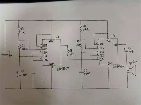
Circuit Diagram
Here is the circuit diagram for the simple siren circuit:
[Insert circuit diagram image here]

How the Simple Siren Circuit Works
The simple siren circuit works as follows:
-
The 555 timer IC acts as an astable multivibrator, generating a square wave signal with a frequency determined by the values of the resistors and the capacitor connected to it.
-
The potentiometer allows you to adjust the frequency of the square wave, which in turn changes the pitch of the siren sound.
-
The output of the 555 timer IC is connected to the base of the transistor, which acts as an amplifier. The transistor switches on and off according to the square wave signal, allowing current to flow through the speaker.
-
The speaker converts the amplified electrical signal into sound waves, producing the characteristic siren wail.
-
The battery provides power to the circuit, and the capacitor helps to filter any noise in the power supply.
Step-by-Step Guide to Building the Simple Siren Circuit
Follow these steps to build the simple siren circuit on a breadboard:
-
Place the 555 timer IC on the breadboard, ensuring that each pin is in a separate row.
-
Connect pin 1 (GND) of the 555 timer IC to the ground rail of the breadboard.
-
Connect pin 8 (VCC) of the 555 timer IC to the positive rail of the breadboard.
-
Connect one end of the 1kΩ resistor to pin 7 (DISCHARGE) of the 555 timer IC and the other end to pin 6 (THRESHOLD).
-
Connect one end of the 10kΩ resistor to pin 6 (THRESHOLD) of the 555 timer IC and the other end to the positive rail.
-
Connect the 10µF capacitor between pin 5 (CONTROL) of the 555 timer IC and the ground rail.
-
Connect one end of the potentiometer to pin 7 (DISCHARGE) of the 555 timer IC, the other end to the positive rail, and the wiper (middle pin) to pin 2 (TRIGGER).
-
Connect the collector of the transistor to one terminal of the speaker and the emitter to the ground rail.
-
Connect pin 3 (OUTPUT) of the 555 timer IC to the base of the transistor.
-
Connect the positive terminal of the battery to the positive rail and the negative terminal to the ground rail.
-
Double-check all connections to ensure they are correct and secure.
-
Turn on the power by connecting the battery, and adjust the potentiometer to change the siren sound.
Troubleshooting Tips
If your simple siren circuit is not working as expected, try these troubleshooting tips:
- Check that all components are properly connected and oriented correctly on the breadboard.
- Ensure that the battery is fresh and supplying the correct voltage.
- Verify that the transistor and 555 timer IC are functioning properly by replacing them with known working components.
- Check for any loose or broken connections, and repair them as necessary.
- If the sound is distorted or weak, try adjusting the values of the resistors or replacing the speaker with one of a different impedance.
Applications of Siren Circuits
Siren circuits have numerous applications, including:
- Emergency vehicles (police cars, ambulances, fire trucks)
- Security systems (burglar alarms, fire alarms)
- Industrial equipment (warning signals, evacuation alerts)
- Toys and novelty devices
- Movie and television sound effects
By modifying the components and values in the simple siren circuit, you can create a wide variety of siren sounds for different applications.
Frequently Asked Questions (FAQ)
-
Q: Can I use a different speaker impedance in the simple siren circuit?
A: Yes, you can use speakers with different impedances, but you may need to adjust the values of the resistors to ensure optimal performance. Lower impedance speakers will draw more current and may require a higher-power transistor. -
Q: How can I change the pitch range of the siren sound?
A: To change the pitch range of the siren sound, you can modify the values of the resistors connected to the 555 timer IC. Increasing the resistance will lower the frequency range, while decreasing the resistance will raise it. -
Q: Is it possible to add multiple speakers to the simple siren circuit?
A: Yes, you can add multiple speakers in parallel to increase the volume of the siren sound. However, keep in mind that adding more speakers will draw more current, so you may need to use a higher-power transistor or a separate amplifier circuit. -
Q: Can I power the simple siren circuit using a DC power supply instead of a battery?
A: Yes, you can use a DC power supply with the appropriate voltage and current ratings to power the simple siren circuit. Make sure to include a power switch and proper fuse protection for safety. -
Q: How can I make the siren sound more realistic or complex?
A: To create more realistic or complex siren sounds, you can experiment with different oscillator circuits, such as multiple 555 timer ICs or microcontrollers programmed to generate specific sound patterns. You can also add filters, modulation, or effects circuits to shape the sound further.
Conclusion
The simple siren circuit is a great introduction to the world of electronic audio circuits. By understanding the basic components and working principle behind a siren circuit, you can create your own custom siren sounds for various applications. Remember to always follow proper safety guidelines and use appropriate components when building electronic circuits.
With this knowledge, you can expand your skills and explore more advanced siren circuits, such as those using microcontrollers or digital signal processing. Happy tinkering!
No responses yet