Introduction to Light Sensor Circuits
A light sensor circuit is an electronic device that detects the presence or absence of light and converts it into an electrical signal. This type of circuit is widely used in various applications, such as automatic lighting control, security systems, and industrial automation. In this article, we will provide a comprehensive guideline on how to build your own light sensor switch circuit.
Understanding the Basic Components
Before diving into the construction of a light sensor circuit, it is essential to understand the basic components that make up the circuit. The main components of a light sensor circuit include:
- Light Dependent Resistor (LDR)
- Resistors
- Transistor
- Relay
- Power Supply
Light Dependent Resistor (LDR)
An LDR, also known as a photoresistor, is a variable resistor whose resistance decreases with increasing incident light intensity. It is the key component in a light sensor circuit, as it detects the presence or absence of light.
Resistors
Resistors are passive electronic components that oppose the flow of electric current in a circuit. In a light sensor circuit, resistors are used to control the current flowing through the LDR and transistor.
Transistor
A transistor is a semiconductor device that amplifies or switches electronic signals and power. In a light sensor circuit, a transistor is used to switch the relay on or off based on the input signal from the LDR.
Relay
A relay is an electrically operated switch that uses an electromagnet to mechanically operate a switch. In a light sensor circuit, a relay is used to control the power supply to the load (e.g., a light bulb or motor) based on the input signal from the transistor.
Power Supply
A power supply is a device that supplies electric power to an electrical load. In a light sensor circuit, a power supply is used to provide the necessary voltage and current to operate the circuit components.
Designing the Light Sensor Circuit
Now that we have a basic understanding of the components involved in a light sensor circuit, let’s move on to designing the circuit.
Circuit Diagram
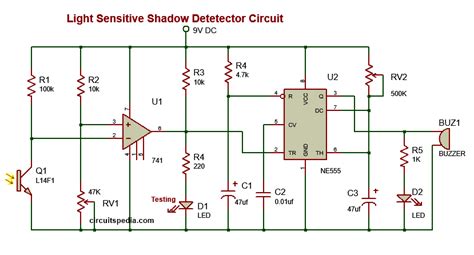
The first step in designing a light sensor circuit is to create a circuit diagram. A circuit diagram is a graphical representation of an electrical circuit, showing how the components are connected. Below is an example circuit diagram for a basic light sensor switch:
Selecting the Components
Once you have the circuit diagram, the next step is to select the appropriate components for your light sensor circuit. Here are some guidelines for selecting the components:
- LDR: Choose an LDR with a resistance range suitable for your application. A common LDR used in light sensor circuits is the GL5516, which has a resistance range of 8-20 kΩ in the dark and 100-1000 Ω in bright light.
- Resistors: Select resistors with appropriate values to control the current flow in the circuit. In the example circuit diagram, a 10 kΩ resistor is used to limit the current through the LDR, and a 1 kΩ resistor is used to bias the transistor.
- Transistor: Choose a transistor with suitable current gain and voltage ratings. A common transistor used in light sensor circuits is the BC547, which has a current gain of 110-800 and a maximum collector-emitter voltage of 45V.
- Relay: Select a relay with an appropriate coil voltage and current rating, as well as suitable contact ratings for switching the load. A common relay used in light sensor circuits is the SRD-05VDC-SL-C, which has a coil voltage of 5V DC and a maximum switching current of 10A.
- Power Supply: Choose a power supply with a voltage and current rating suitable for your circuit components. In the example circuit diagram, a 5V DC power supply is used to power the circuit.
Calculating Component Values
To ensure that your light sensor circuit functions correctly, it is important to calculate the appropriate values for the components. Here are some basic calculations you can use:
- LDR Voltage Divider: The voltage across the LDR in the voltage divider circuit can be calculated using the formula:
V_LDR = V_CC * (R_LDR / (R_LDR + R1))
where V_CC is the supply voltage, R_LDR is the resistance of the LDR, and R1 is the fixed resistor value. - Transistor Base Current: The base current required to saturate the transistor can be calculated using the formula:
I_B = (V_CC - V_BE) / R2
where V_BE is the base-emitter voltage drop (typically 0.7V for silicon transistors), and R2 is the base resistor value. - Relay Coil Current: The current through the relay coil can be calculated using Ohm’s law:
I_Coil = V_Coil / R_Coil
where V_Coil is the coil voltage, and R_Coil is the coil resistance.

Constructing the Light Sensor Circuit
With the circuit design and component selection complete, it’s time to start building your light sensor circuit.
Step-by-Step Guide
- Gather all the necessary components and tools, such as a breadboard, jumper wires, soldering iron, and multimeter.
- Place the components on the breadboard according to the circuit diagram.
- Connect the components using jumper wires, ensuring that the polarity of the components is correct.
- Double-check all connections to avoid short circuits or incorrect wiring.
- Power on the circuit and test its functionality by exposing the LDR to different light conditions.
- If the circuit does not function as expected, troubleshoot by checking the connections and component values.
- Once the circuit is working satisfactorily, you can transfer it to a permanent prototyping board or PCB for long-term use.
Tips and Precautions
- Always handle electronic components with care, as they can be easily damaged by static electricity or improper handling.
- Use a multimeter to check the continuity and resistance of the components before connecting them in the circuit.
- Ensure that the power supply voltage and current ratings are compatible with your circuit components to avoid damage.
- Use heat shrink tubing or insulating tape to cover exposed wire connections and prevent short circuits.
- Test the circuit in a safe environment, away from flammable materials or moisture.

Applications of Light Sensor Circuits
Light sensor circuits find applications in various fields, such as:
Automatic Lighting Control
Light sensor circuits can be used to automatically turn on or off lights based on the ambient light conditions. This can help save energy and provide convenience in both residential and commercial settings.
Security Systems
Light sensor circuits can be integrated into security systems to detect unauthorized access or intrusion. For example, a light sensor can trigger an alarm or camera when a sudden change in light intensity is detected, indicating the presence of an intruder.
Industrial Automation
In industrial settings, light sensor circuits can be used to monitor and control various processes. For example, a light sensor can detect the presence of an object on a conveyor belt and trigger a sorting mechanism or stop the belt if an anomaly is detected.
Environmental Monitoring
Light sensor circuits can be used in environmental monitoring applications, such as measuring the intensity of sunlight for solar energy systems or monitoring the growth of plants in greenhouses.

Troubleshooting Common Issues
While building and using a light sensor circuit, you may encounter some common issues. Here are a few troubleshooting tips:
Circuit Not Responding to Light Changes
- Check the connections and ensure that the LDR is properly connected in the voltage divider configuration.
- Verify that the transistor is biased correctly and that the base current is sufficient to saturate the transistor.
- Ensure that the relay coil voltage and current ratings are compatible with the transistor and power supply.
False Triggering
- Adjust the sensitivity of the circuit by changing the value of the fixed resistor in the voltage divider. Increasing the resistance will make the circuit more sensitive to light changes.
- Use a Schmitt trigger circuit to provide hysteresis and prevent false triggering due to noise or slight fluctuations in light intensity.
Relay Chattering
- Use a snubber circuit, consisting of a resistor and capacitor in series, across the relay coil to suppress voltage spikes and prevent chattering.
- Ensure that the relay contacts are rated for the load current and voltage to avoid arcing or welding of the contacts.
FAQ
-
What is the purpose of a light sensor circuit?
A light sensor circuit detects the presence or absence of light and converts it into an electrical signal, which can be used to control various devices or trigger actions based on the light conditions. -
How does an LDR work in a light sensor circuit?
An LDR (Light Dependent Resistor) is a variable resistor whose resistance decreases with increasing light intensity. In a light sensor circuit, the LDR is used to detect changes in the ambient light level and provide a corresponding voltage signal to the rest of the circuit. -
Can I use any transistor in a light sensor circuit?
While you can use different types of transistors in a light sensor circuit, it is important to choose a transistor with suitable current gain and voltage ratings for your specific application. The BC547 transistor is a common choice for light sensor circuits due to its high current gain and low cost. -
How do I adjust the sensitivity of a light sensor circuit?
The sensitivity of a light sensor circuit can be adjusted by changing the value of the fixed resistor in the voltage divider configuration. Increasing the resistance will make the circuit more sensitive to light changes, while decreasing the resistance will make it less sensitive. -
Can I power a light sensor circuit directly from mains voltage?
No, it is not recommended to power a light sensor circuit directly from mains voltage (110V/220V AC) due to safety concerns and the risk of damage to the components. Instead, use a step-down transformer and rectifier circuit to convert the mains voltage to a lower DC voltage suitable for your circuit, typically 5V or 12V DC.
Conclusion
Building a light sensor switch circuit is a simple yet effective way to introduce yourself to the world of electronics and automation. By understanding the basic components, designing the circuit, and following the construction guidelines, you can create a functional light sensor circuit for various applications.
Remember to always prioritize safety and follow proper precautions while working with electronic components. With practice and experimentation, you can further enhance your skills and explore more advanced light sensor circuits and applications.
No responses yet