What is a PCB File?
A PCB file, short for Printed Circuit Board file, is a digital document that contains all the necessary information required to manufacture a physical printed circuit board. It is a critical component in the electronic design process, as it serves as the blueprint for the fabrication and assembly of the PCB.
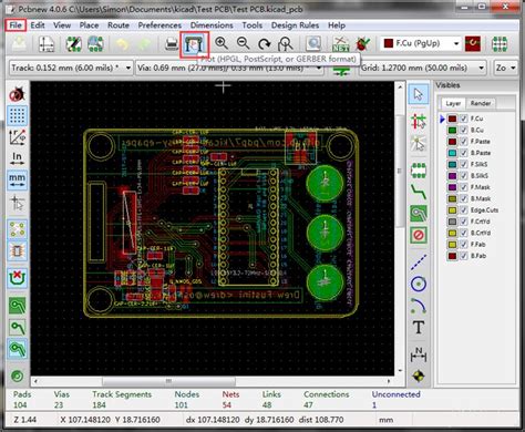
PCB files are created using specialized electronic design automation (EDA) software, such as Altium Designer, KiCad, or Eagle. These software tools allow engineers and designers to create schematic diagrams, layout the PCB, and generate the necessary files for manufacturing.
Types of PCB Files
There are several types of PCB files, each serving a specific purpose in the manufacturing process. Some of the most common types include:
-
Gerber Files: These are the most widely used PCB files and contain information about the copper layers, solder mask, silkscreen, and drill holes. Gerber files are named after their creator, H. Joseph Gerber, and have a .gbr file extension.
-
Drill Files: These files contain information about the location, size, and type of holes to be drilled in the PCB. They are typically in Excellon format and have a .drl file extension.
-
NC Files: Numerical Control (NC) files are used to control the machines that drill holes and route the PCB. They contain G-code instructions for the machines and have a .nc file extension.
-
BOM Files: Bill of Materials (BOM) files contain a list of all the components used in the PCB, along with their quantities, part numbers, and other relevant information. They are typically in CSV or Excel format.
-
Pick and Place Files: These files contain information about the placement of components on the PCB, including their coordinates and orientation. They are used by pick and place machines during the assembly process.
Why are PCB Files Important?
PCB files are essential for several reasons:
-
Manufacturing: PCB files are the primary source of information for PCB manufacturers. They use these files to create the physical PCB, ensuring that it meets the designer’s specifications.
-
Communication: PCB files serve as a common language between designers, manufacturers, and assemblers. They ensure that everyone involved in the process has access to the same information, reducing the risk of errors and misunderstandings.
-
Documentation: PCB files provide a comprehensive record of the PCB design, including its schematic, layout, and component information. This documentation is valuable for future reference, troubleshooting, and modifications.
-
Quality Control: By adhering to industry standards and best practices when creating PCB files, designers can ensure that their boards are manufacturable and meet the required quality standards.

How to Create PCB Files
Creating PCB files involves several steps, each requiring specific skills and tools. Here’s a general overview of the process:
-
Schematic Design: The first step is to create a schematic diagram of the circuit using EDA software. This involves selecting components, defining their connections, and adding necessary information such as part numbers and values.
-
PCB Layout: Once the schematic is complete, the next step is to lay out the components on the PCB. This involves placing components, routing traces, and defining the board’s outline and mounting holes.
-
Design Rule Check (DRC): After the layout is complete, it’s important to run a DRC to ensure that the design meets the manufacturer’s specifications and industry standards. This helps to identify and correct any errors or potential issues before manufacturing.
-
File Generation: Once the design is finalized, the necessary files for manufacturing can be generated. This typically involves exporting Gerber files, drill files, and other relevant files from the EDA software.
-
File Verification: Before sending the files to the manufacturer, it’s crucial to verify that they are correct and complete. This can be done using specialized software tools that check for common errors and inconsistencies.

Best Practices for Creating PCB Files
To ensure that your PCB files are accurate, complete, and manufacturable, follow these best practices:
-
Use a consistent naming convention for your files, including the board name, version number, and file type.
-
Include all necessary layers in your Gerber files, such as copper, solder mask, silkscreen, and drill layers.
-
Use a standard format for your drill files, such as Excellon.
-
Include a readme file with your PCB files that provides additional information and instructions for the manufacturer.
-
Verify your files using specialized software tools before sending them to the manufacturer.

Common PCB File Formats and Extensions
| File Type | Extension | Description |
|---|---|---|
| Gerber | .gbr | Contains information about the copper layers, solder mask, silkscreen, and drill holes |
| Drill | .drl | Contains information about the location, size, and type of holes to be drilled in the PCB |
| NC | .nc | Contains G-code instructions for machines that drill holes and route the PCB |
| BOM | .csv, .xls | Contains a list of all the components used in the PCB, along with their quantities and part numbers |
| Pick and Place | .csv, .txt | Contains information about the placement of components on the PCB, including their coordinates and orientation |
FAQ
-
Q: Can I use any EDA software to create PCB files?
A: While there are many EDA software options available, it’s important to choose one that is widely supported by PCB manufacturers and has the necessary features for your project. Some popular options include Altium Designer, KiCad, and Eagle. -
Q: What happens if I send incorrect or incomplete PCB files to the manufacturer?
A: Sending incorrect or incomplete PCB files can result in delays, additional costs, and even unusable boards. It’s essential to verify your files before sending them to the manufacturer to avoid these issues. -
Q: How do I choose the right PCB manufacturer for my project?
A: When choosing a PCB manufacturer, consider factors such as their experience, capabilities, quality control processes, and customer support. It’s also important to ensure that they can handle the specific requirements of your project, such as the number of layers, material type, and surface finish. -
Q: What is the difference between Gerber files and NC files?
A: Gerber files contain information about the copper layers, solder mask, silkscreen, and drill holes, while NC files contain G-code instructions for the machines that drill holes and route the PCB. Both file types are necessary for manufacturing, but they serve different purposes. -
Q: Can I modify PCB files after they have been sent to the manufacturer?
A: In most cases, modifying PCB files after they have been sent to the manufacturer will result in additional costs and delays. It’s best to ensure that your files are complete and accurate before sending them to avoid the need for modifications.
Conclusion
PCB files are a critical component in the electronic design and manufacturing process. They serve as the blueprint for the fabrication and assembly of physical printed circuit boards, ensuring that the final product meets the designer’s specifications and industry standards.
Creating accurate and complete PCB files requires a combination of technical skills, specialized software tools, and attention to detail. By following best practices and verifying your files before sending them to the manufacturer, you can minimize the risk of errors, delays, and additional costs.
As the electronics industry continues to evolve, the importance of PCB files will only continue to grow. By understanding the different types of PCB files, their purposes, and how to create them effectively, you can streamline your design process and ensure the success of your electronic projects.
No responses yet