What is the MPU6050?
The MPU6050 is a 6-axis motion tracking device developed by InvenSense. It features a 3-axis gyroscope and a 3-axis accelerometer, enabling it to measure angular velocity and linear acceleration in three dimensions. The sensor also includes an onboard Digital Motion Processor (DMP) that can perform complex calculations and data fusion, offloading these tasks from the main microcontroller.
Key features of the MPU6050:
- 3-axis gyroscope with a programmable full-scale range of ±250, ±500, ±1000, and ±2000 °/sec
- 3-axis accelerometer with a programmable full-scale range of ±2, ±4, ±8, and ±16 g
- Digital Motion Processor (DMP) for advanced motion processing
- I2C digital output interface
- 16-bit ADC for each channel
- Low power consumption
- Compact QFN package measuring 4x4x0.9 mm
MPU6050 Pinout
The MPU6050 comes in a 24-pin QFN (Quad-Flat No-leads) package. Understanding the pinout is crucial for properly connecting the sensor to your microcontroller or development board.
| Pin Number | Pin Name | Description |
|---|---|---|
| 1 | CLKIN | External clock input |
| 2 | AD0 | I2C slave address LSB |
| 3 | REGOUT | Regulator output |
| 4 | FSYNC | Frame synchronization digital input |
| 5 | INT | Interrupt digital output |
| 6 | VDD | Power supply (2.375V to 3.46V) |
| 7 | GND | Ground |
| 8-11 | N/C | No connect |
| 12 | RESV | Reserved |
| 13 | CPOUT | Charge pump capacitor |
| 14-23 | N/C | No connect |
| 24 | SDA/SDI | I2C serial data / SPI serial data input |
| 25 | SCL/SCLK | I2C serial clock / SPI serial clock |
Important pins for basic operation:
- VDD: Connect to a stable power supply between 2.375V and 3.46V.
- GND: Connect to the ground of your system.
- SDA/SDI: Connect to the I2C data line or SPI data input of your microcontroller.
- SCL/SCLK: Connect to the I2C clock line or SPI clock of your microcontroller.
- INT: Optional interrupt pin that can be connected to your microcontroller for event-driven communication.
- AD0: Used to set the I2C slave address. Connect to VDD or GND to set the LSB of the address.

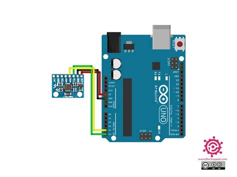
Connecting the MPU6050 to an Arduino
To demonstrate how to connect the MPU6050 to a microcontroller, we’ll use an Arduino Uno as an example.
- Connect VDD to the 3.3V pin on the Arduino.
- Connect GND to one of the GND pins on the Arduino.
- Connect SDA/SDI to the A4 pin (or SDA pin) on the Arduino.
- Connect SCL/SCLK to the A5 pin (or SCL pin) on the Arduino.
- Optionally, connect INT to a digital pin on the Arduino if you want to use interrupts.
| MPU6050 Pin | Arduino Pin |
|---|---|
| VDD | 3.3V |
| GND | GND |
| SDA/SDI | A4 (SDA) |
| SCL/SCLK | A5 (SCL) |
| INT | Digital Pin (optional) |

Configuring the MPU6050
Before you can start using the MPU6050, you need to configure it using the I2C interface. The most important settings include:
- Setting the gyroscope and accelerometer full-scale ranges
- Configuring the Digital Low-Pass Filter (DLPF)
- Enabling or disabling the DMP
- Setting the sample rate divider
Here’s an example of how to configure the MPU6050 using the Arduino Wire library:
#include <Wire.h>

const int MPU_addr = 0x68;

void setup() {
  Wire.begin();
  Wire.beginTransmission(MPU_addr);
  Wire.write(0x6B);  // PWR_MGMT_1 register
  Wire.write(0);     // Wake up the MPU-6050
  Wire.endTransmission(true);

  // Configure the accelerometer range
  Wire.beginTransmission(MPU_addr);
  Wire.write(0x1C);  // ACCEL_CONFIG register
  Wire.write(0x10);  // Set to ±8g full-scale range
  Wire.endTransmission(true);

  // Configure the gyroscope range
  Wire.beginTransmission(MPU_addr);
  Wire.write(0x1B);  // GYRO_CONFIG register
  Wire.write(0x18);  // Set to ±2000°/s full-scale range
  Wire.endTransmission(true);
}

void loop() {
  // Your main code here
}

Reading Data from the MPU6050
Once the MPU6050 is configured, you can start reading accelerometer and gyroscope data using the I2C interface. The raw data is stored in 16-bit registers, which you need to concatenate and convert to meaningful units.
Here’s an example of how to read raw accelerometer and gyroscope data:
void loop() {
  Wire.beginTransmission(MPU_addr);
  Wire.write(0x3B);  // Starting with register 0x3B (ACCEL_XOUT_H)
  Wire.endTransmission(false);
  Wire.requestFrom(MPU_addr, 14, true); // Request a total of 14 registers

  // Accelerometer data
  int16_t AcX = Wire.read() << 8 | Wire.read();
  int16_t AcY = Wire.read() << 8 | Wire.read();
  int16_t AcZ = Wire.read() << 8 | Wire.read();

  // Gyroscope data
  int16_t GyX = Wire.read() << 8 | Wire.read();
  int16_t GyY = Wire.read() << 8 | Wire.read();
  int16_t GyZ = Wire.read() << 8 | Wire.read();
}
To convert the raw data to meaningful units, you need to divide the raw values by the appropriate scale factors based on the configured full-scale ranges.
For example, if the accelerometer is set to a full-scale range of ±8g, the scale factor is 4096 LSB/g. To convert the raw accelerometer data to g:
float accel_x = AcX / 4096.0;
float accel_y = AcY / 4096.0;
float accel_z = AcZ / 4096.0;
Similarly, if the gyroscope is set to a full-scale range of ±2000°/s, the scale factor is 16.4 LSB/°/s. To convert the raw gyroscope data to °/s:
float gyro_x = GyX / 16.4;
float gyro_y = GyY / 16.4;
float gyro_z = GyZ / 16.4;
Using the Digital Motion Processor (DMP)
The MPU6050’s onboard Digital Motion Processor (DMP) can perform complex motion processing tasks, such as sensor fusion and quaternion calculations. Using the DMP can offload these computationally intensive tasks from your main microcontroller, resulting in improved performance and reduced power consumption.
To use the DMP, you need to load the firmware onto the MPU6050 and configure it using the I2C interface. The DMP firmware is proprietary and not openly available, but there are several libraries that include the necessary firmware and provide high-level functions for interacting with the DMP.
One popular library for working with the MPU6050 and its DMP is the “MPU6050_6Axis_MotionApps20.h” library by Jeff Rowberg. This library includes the DMP firmware and provides functions for initializing the DMP, reading quaternion data, and more.
Here’s an example of how to initialize the DMP using the “MPU6050_6Axis_MotionApps20.h” library:
#include "I2Cdev.h"
#include "MPU6050_6Axis_MotionApps20.h"

MPU6050 mpu;

void setup() {
  Wire.begin();
  mpu.initialize();

  if (mpu.dmpInitialize() == 0) {
    mpu.setDMPEnabled(true);
  }
}
Once the DMP is initialized and enabled, you can read quaternion data using the dmpGetQuaternion() function:
Quaternion q;

void loop() {
  if (mpu.dmpGetCurrentFIFOPacket(fifoBuffer)) {
    mpu.dmpGetQuaternion(&q, fifoBuffer);
  }
}
The quaternion data represents the orientation of the MPU6050 in 3D space and can be used for various applications, such as attitude estimation, sensor fusion, and motion tracking.
Troubleshooting Common Issues
-
Incorrect wiring: Double-check your connections to ensure that the MPU6050 is properly connected to your microcontroller. Pay special attention to the VDD, GND, SDA, and SCL pins.
-
I2C address conflicts: If you have multiple I2C devices connected to your microcontroller, ensure that each device has a unique address. The MPU6050’s I2C address can be set using the AD0 pin (0x68 when AD0 is low, 0x69 when AD0 is high).
-
Incorrect configuration: Make sure you have properly configured the MPU6050’s registers, including the gyroscope and accelerometer full-scale ranges, DLPF settings, and sample rate divider.
-
DMP initialization failure: If the DMP initialization fails, check that you have loaded the correct firmware and that the MPU6050 is properly connected. You may also need to adjust the DMP settings in your code.
-
Noisy or inconsistent data: If you experience noisy or inconsistent data, try adjusting the DLPF settings to reduce high-frequency noise. You can also experiment with different full-scale ranges to find the optimal balance between resolution and range.
Conclusion
The MPU6050 is a powerful and versatile 6-axis motion tracking device that can be used in a wide range of applications. By understanding the MPU6050 pinout and how to configure and read data from the sensor, you can effectively integrate it into your projects. Remember to pay attention to wiring, I2C address conflicts, and proper configuration to ensure optimal performance. With the MPU6050 and the right tools, you can create innovative motion tracking applications and bring your ideas to life.
Frequently Asked Questions (FAQ)
-
What is the difference between the MPU6050 and the MPU9250?
The MPU6050 is a 6-axis motion tracking device that includes a 3-axis gyroscope and a 3-axis accelerometer. The MPU9250, on the other hand, is a 9-axis motion tracking device that includes a 3-axis gyroscope, a 3-axis accelerometer, and a 3-axis magnetometer. The MPU9250 provides additional functionality for measuring magnetic fields and performing more advanced sensor fusion. -
Can I use the MPU6050 with a 5V microcontroller?
The MPU6050 is designed to operate with a power supply between 2.375V and 3.46V. While it is possible to use the MPU6050 with a 5V microcontroller, you must use a level shifter to convert the 5V I2C signals to the appropriate voltage level for the MPU6050. Connecting the MPU6050 directly to a 5V microcontroller without a level shifter can damage the sensor. -
How do I set the I2C address of the MPU6050?
The MPU6050’s I2C address can be set using the AD0 pin. When AD0 is connected to GND, the I2C address is 0x68. When AD0 is connected to VDD, the I2C address is 0x69. Make sure to use the correct address in your code when initializing the I2C communication. -
What is the maximum sample rate of the MPU6050?
The MPU6050’s maximum sample rate depends on the selected Digital Low-Pass Filter (DLPF) setting. With the DLPF disabled, the maximum sample rate is 8 kHz for the gyroscope and 1 kHz for the accelerometer. However, using such high sample rates may not be practical for most applications, as it can generate a large amount of data and require significant processing power. It’s generally recommended to use a sample rate that balances your application’s requirements with the available processing resources. -
Can I use the MPU6050 for gesture recognition?
Yes, the MPU6050 can be used for gesture recognition applications. By combining the gyroscope and accelerometer data, you can detect and classify various gestures, such as tilting, shaking, or rotating the sensor. To achieve accurate gesture recognition, you may need to implement advanced signal processing techniques, such as pattern matching, machine learning, or sensor fusion. Additionally, using the MPU6050’s Digital Motion Processor (DMP) can help offload some of the computation from your main microcontroller, making gesture recognition more efficient and responsive.
No responses yet