What is Insufficient Solder?
Insufficient solder occurs when there is not enough solder present to create a strong, reliable connection between the component and the printed circuit board (PCB). This can happen due to various reasons, such as:
- Incorrect solder paste stencil design or thickness
- Improper solder paste application
- Incorrect reflow oven settings
- Component placement issues
- Inadequate cleaning of the PCB or components before soldering
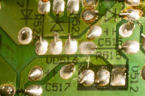
When there is insufficient solder, the connection may appear dull, grainy, or incomplete. In some cases, the component may not be properly attached to the PCB at all.
Causes of Insufficient Solder
Incorrect Solder Paste Stencil Design or Thickness
The solder paste stencil is responsible for applying the correct amount of solder paste to the PCB pads. If the stencil apertures are too small or the stencil is too thin, there may not be enough solder paste deposited, leading to insufficient solder.
Improper Solder Paste Application
Even with the correct stencil design and thickness, improper solder paste application can cause insufficient solder. This can happen if:
- The solder paste is not mixed properly before use
- The solder paste is too cold or too warm during application
- The squeegee pressure or speed is incorrect
- The stencil is not cleaned regularly, causing clogging of the apertures
Incorrect Reflow Oven Settings
The reflow oven is responsible for melting the solder paste and creating the solder joint. If the oven settings are incorrect, the solder may not melt completely, resulting in insufficient solder. Common issues include:
- Peak temperature is too low
- Time above liquidus (TAL) is too short
- Ramp rate is too slow
- Cooling rate is too fast
Component Placement Issues
If components are not placed accurately on the PCB pads, there may not be enough contact with the solder paste, leading to insufficient solder. This can happen due to:
- Incorrect pick-and-place machine settings
- Bent or misaligned component leads
- Incorrect component polarity or orientation
Inadequate Cleaning of the PCB or Components
Contaminants on the PCB or component surfaces can prevent the solder from properly wetting and adhering. This can lead to insufficient solder. Common contaminants include:
- Oxides
- Flux residues
- Dirt and debris
- Fingerprints and oils

Preventing Insufficient Solder
To prevent insufficient solder, it’s essential to follow best practices in each stage of the electronic manufacturing process.
Solder Paste Stencil Design and Thickness
- Ensure that the stencil apertures are the correct size and shape for the component pads
- Use the appropriate stencil thickness for the solder paste and components being used (typically 4-6 mils for standard SMT components)
- Regularly inspect and maintain the stencil to ensure it is not damaged or clogged
Solder Paste Application
- Mix the solder paste thoroughly before use to ensure consistent viscosity and particle distribution
- Maintain the solder paste at the recommended temperature during application (typically 68-77°F or 20-25°C)
- Use the correct squeegee pressure and speed for the solder paste and stencil being used
- Clean the stencil regularly to prevent clogging of the apertures
Reflow Oven Settings
- Follow the solder paste manufacturer’s recommended reflow profile for the specific paste being used
- Ensure that the peak temperature is high enough to fully melt the solder (typically 20-40°C above the solder’s melting point)
- Maintain sufficient time above liquidus (TAL) to allow the solder to wet and spread (typically 60-90 seconds)
- Use an appropriate ramp rate to avoid thermal shock to the components (typically 1-3°C/second)
- Control the cooling rate to allow the solder to solidify properly (typically 1-4°C/second)
Component Placement
- Ensure that the pick-and-place machine is properly calibrated and programmed for the specific components being used
- Inspect component leads for bent or misaligned pins before placement
- Verify component polarity and orientation before placement
- Use vision systems to confirm accurate component placement
PCB and Component Cleaning
- Clean the PCB and components before solder paste application to remove any contaminants
- Use appropriate cleaning agents and methods for the specific contaminants and materials involved
- Allow sufficient drying time after cleaning to ensure no moisture remains on the surfaces

Fixing Insufficient Solder
If insufficient solder is detected after the reflow process, there are several methods to fix the issue, depending on the severity and location of the problem.
Manual Soldering
For small-scale repairs or rework, manual soldering can be used to add more solder to the joint. This involves:
- Applying flux to the joint to help the solder flow and wet the surfaces
- Heating the joint with a soldering iron to reflow the existing solder
- Adding a small amount of solder wire to the joint to increase the solder volume
- Inspecting the joint to ensure proper wetting and shape
Solder Paste Dispensing
For larger-scale repairs or hard-to-reach areas, solder paste dispensing can be used to add more solder paste to the joint before reflowing. This involves:
- Cleaning the joint area to remove any debris or contamination
- Applying a small amount of solder paste to the joint using a dispenser or syringe
- Reflowing the solder paste using a localized heat source (hot air, laser, etc.)
- Inspecting the joint to ensure proper wetting and shape
Selective Soldering
For more complex repairs or high-volume production, selective soldering can be used to add solder to specific areas of the PCB. This involves:
- Programming the selective soldering machine with the specific locations and parameters for the repair
- Applying flux to the joint areas to be soldered
- Using a miniature wave or laser soldering head to apply solder to the joint
- Inspecting the joint to ensure proper wetting and shape

Prevention is Key
While there are methods to fix insufficient solder, the best approach is to prevent the issue from occurring in the first place. By following best practices in solder paste stencil design, solder paste application, reflow oven settings, component placement, and PCB and component cleaning, you can minimize the risk of insufficient solder and ensure reliable, high-quality solder joints.
Regular process monitoring and control are also essential to maintaining consistent solder joint quality. This includes:
- Periodic inspection of solder paste stencils for damage or clogging
- Monitoring of solder paste viscosity and performance
- Verification of reflow oven temperature profiles and settings
- Automated optical inspection (AOI) of solder joints after reflow
- Cross-sectional analysis of solder joints to verify internal structure and quality
By implementing these prevention and monitoring measures, you can significantly reduce the occurrence of insufficient solder and improve the overall reliability and performance of your electronic assemblies.
Frequently Asked Questions (FAQ)
1. What are the most common causes of insufficient solder?
The most common causes of insufficient solder include incorrect solder paste stencil design or thickness, improper solder paste application, incorrect reflow oven settings, component placement issues, and inadequate cleaning of the PCB or components before soldering.
2. How can I tell if a solder joint has insufficient solder?
A solder joint with insufficient solder may appear dull, grainy, or incomplete. In some cases, the component may not be properly attached to the PCB. Visual inspection, automated optical inspection (AOI), and cross-sectional analysis can be used to identify insufficient solder joints.
3. What is the best way to prevent insufficient solder?
The best way to prevent insufficient solder is to follow best practices in each stage of the electronic manufacturing process, including solder paste stencil design and thickness, solder paste application, reflow oven settings, component placement, and PCB and component cleaning. Regular process monitoring and control are also essential.
4. Can insufficient solder be fixed after the reflow process?
Yes, insufficient solder can be fixed after the reflow process using methods such as manual soldering, solder paste dispensing, or selective soldering, depending on the severity and location of the issue.
5. What are the consequences of not addressing insufficient solder?
Not addressing insufficient solder can lead to poor connections, decreased reliability, and even complete failure of the circuit. This can result in increased costs due to rework, repairs, or product returns, as well as damage to the manufacturer’s reputation and customer satisfaction.
| Cause of Insufficient Solder | Prevention Measures |
|---|---|
| Incorrect solder paste stencil design or thickness | – Ensure correct aperture size and shape – Use appropriate stencil thickness – Regularly inspect and maintain stencil |
| Improper solder paste application | – Mix paste thoroughly before use – Maintain recommended temperature – Use correct squeegee pressure and speed – Clean stencil regularly |
| Incorrect reflow oven settings | – Follow manufacturer’s recommended profile – Ensure sufficient peak temperature and TAL – Use appropriate ramp and cooling rates |
| Component placement issues | – Calibrate and program pick-and-place machine – Inspect component leads before placement – Verify polarity and orientation – Use vision systems for accuracy |
| Inadequate cleaning of PCB or components | – Clean PCB and components before paste application – Use appropriate cleaning agents and methods – Allow sufficient drying time after cleaning |
By understanding the causes of insufficient solder and implementing the appropriate prevention measures, electronic manufacturers can significantly improve the quality and reliability of their solder joints, leading to better product performance and customer satisfaction.
No responses yet