Key Features of the MCP6004 op-amp
The MCP6004 stands out among other op-amps due to its impressive set of features:
-
Quad Op-Amp Package: The MCP6004 integrates four independent operational amplifiers in a single chip, allowing for space-saving and cost-effective designs.
-
Rail-to-Rail Input and Output: With rail-to-rail input and output capability, the MCP6004 can operate with input signals close to the supply voltages and generate output signals that swing nearly to the supply rails.
-
Low Bias Current: The op-amp boasts a low input bias current of only 1 pA (typical), minimizing the loading effect on high-impedance signal sources.
-
Wide Supply Voltage Range: The MCP6004 can operate with a single supply voltage ranging from 1.8V to 6.0V, or dual supplies ranging from ±0.9V to ±3.0V, providing flexibility in power supply design.
-
Unity-Gain Stable: Each op-amp in the MCP6004 is unity-gain stable, allowing for easy implementation of buffer and unity-gain follower circuits.
-
Low Noise: With a low input noise voltage of 8.7 nV/√Hz (typical) at 1 kHz, the MCP6004 is suitable for low-noise analog signal processing applications.
MCP6004 Datasheet: Key Specifications
To effectively utilize the MCP6004 in your designs, it’s crucial to understand its key specifications. Let’s take a closer look at some of the important parameters from the datasheet:
Electrical Characteristics
| Parameter | Symbol | Conditions | Min | Typ | Max | Units |
|---|---|---|---|---|---|---|
| Input Offset Voltage | VOS | VCM = VCC/2 | – | 2 | 7 | mV |
| Input Bias Current | IB | VCM = VCC/2 | – | 1 | 30 | pA |
| Input Offset Current | IOS | VCM = VCC/2 | – | 0.5 | 10 | pA |
| Input Common-Mode Voltage Range | VICM | VS = 2.5V to 5.5V | VSS | VCC – 1.5 | V | |
| Open-Loop Gain | AOL | RL = 10 kΩ to VCC/2, VO = 1.4V to VCC – 1.4V | 100 | 126 | – | dB |
| Gain-Bandwidth Product | GBW | RL = 10 kΩ to VCC/2, VO = 1.4V to VCC – 1.4V | – | 1.5 | – | MHz |
| Slew Rate | SR | RL = 10 kΩ to VCC/2, VO = 0.2V to VCC – 0.2V | – | 0.7 | – | V/μs |
These electrical characteristics provide a glimpse into the MCP6004’s performance in terms of input offset voltage, bias current, common-mode voltage range, open-loop gain, gain-bandwidth product, and slew rate.
Operating Conditions
| Parameter | Symbol | Min | Max | Units |
|---|---|---|---|---|
| Supply Voltage (Single) | VCC | 1.8 | 6.0 | V |
| Supply Voltage (Dual) | VS | ±0.9 | ±3.0 | V |
| Operating Temperature Range | TA | -40 | 125 | °C |
The MCP6004 can operate with a single supply voltage from 1.8V to 6.0V or dual supplies from ±0.9V to ±3.0V. It has a wide operating temperature range from -40°C to 125°C, making it suitable for various environmental conditions.

Typical Application Circuits
The MCP6004 can be used in a wide variety of analog circuit applications. Let’s explore a few typical application circuits:
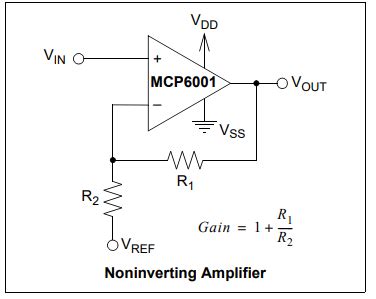
Non-Inverting Amplifier
A non-inverting amplifier configuration using the MCP6004 can provide voltage gain while maintaining high input impedance. The gain is set by the ratio of the feedback resistor (R2) to the input resistor (R1):
Gain = 1 + (R2 / R1)
Here’s an example schematic of a non-inverting amplifier with a gain of 11:
          +VCC
           |
          +-+
          |R2
          |10k
Input---+-+---------+---Output
        |  |        |
        R1 +--------|
        1k |        |
          +-+      +-+
           |        |
          GND      GND
Voltage Follower (Buffer)
A voltage follower, also known as a unity-gain buffer, provides high input impedance and low output impedance, making it useful for isolating stages or driving low-impedance loads. The MCP6004’s rail-to-rail output capability ensures that the output closely follows the input voltage.
Here’s an example schematic of a voltage follower:
          +VCC
           |
          +-+
Input-----+-+-------+---Output
          |         |
          +-+      +-+
           |        |
          GND      GND
Differential Amplifier
A differential amplifier amplifies the difference between two input signals while rejecting common-mode noise. The MCP6004 can be used to implement a differential amplifier with a high common-mode rejection ratio (CMRR).
Here’s an example schematic of a differential amplifier:
          +VCC
           |
          +-+
          |R3
          |10k
         +-+-+----+---Output
         |   |    |
Input1---+---+--+-+
         R1  R2 |
         10k 10k|
Input2---+---+  +-+
               |
               |
              GND
The differential gain is set by the ratio of R3 to R1 (or R2):
Differential Gain = R3 / R1 = R3 / R2

PCB Layout Considerations
To achieve optimal performance with the MCP6004, consider the following PCB layout guidelines:
- Keep the input and output traces as short as possible to minimize stray capacitance and noise pickup.
- Use a ground plane to provide a low-impedance return path for the op-amp and to shield sensitive traces from noise.
- Decouple the power supply pins with ceramic capacitors placed close to the op-amp package.
- Avoid running high-frequency or high-current traces near the op-amp’s input and output pins to reduce crosstalk and interference.
- If using the op-amp in a high-gain configuration, consider adding a small capacitor (e.g., 1 pF to 10 pF) in parallel with the feedback resistor to improve stability and reduce noise.

Frequently Asked Questions (FAQ)
1. What is the maximum supply voltage for the MCP6004?
The MCP6004 can operate with a single supply voltage up to 6.0V or dual supplies up to ±3.0V.
2. Is the MCP6004 unity-gain stable?
Yes, each op-amp in the MCP6004 is unity-gain stable, allowing for easy implementation of buffer and unity-gain follower circuits.
3. What is the typical input bias current of the MCP6004?
The MCP6004 has a low input bias current of only 1 pA (typical), which minimizes the loading effect on high-impedance signal sources.
4. Can the MCP6004 be used in single-supply applications?
Yes, the MCP6004 can operate with a single supply voltage ranging from 1.8V to 6.0V, making it suitable for single-supply applications.
5. What is the operating temperature range of the MCP6004?
The MCP6004 has a wide operating temperature range from -40°C to 125°C, allowing it to be used in various environmental conditions.
Conclusion
The MCP6004 is a versatile and high-performance quad op-amp that offers a wide range of features, including rail-to-rail input and output, low bias current, and wide supply voltage range. By understanding the key specifications and typical application circuits from the MCP6004 datasheet, designers can effectively utilize this op-amp in their analog designs. With proper PCB layout considerations and an understanding of the device’s capabilities, the MCP6004 can provide reliable and efficient performance in a variety of applications, from audio signal processing to sensor conditioning and beyond.
No responses yet