Introduction to Zener Diodes
Zener diodes are a special type of semiconductor diode designed to operate in the reverse breakdown region, providing a stable reference voltage. These diodes are widely used in various electronic applications, such as voltage regulation, overvoltage protection, and voltage clamping. Understanding the characteristics and functionality of Zener diodes is crucial for engineers and hobbyists working with electronic circuits.
In this article, we will explore the construction of a Zener Diode Tester circuit and delve into how it works. By the end of this article, you will have a comprehensive understanding of the Zener diode tester and be able to build one yourself.
What is a Zener Diode Tester?
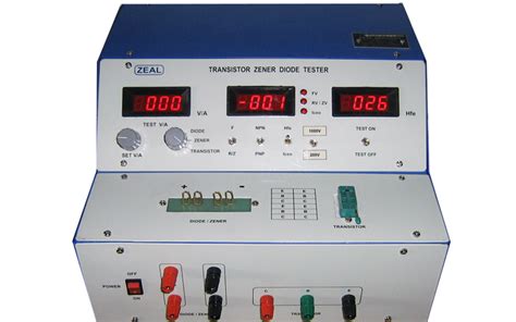
A Zener diode tester is an electronic circuit designed to measure the breakdown voltage and test the functionality of Zener diodes. It provides a convenient way to determine the voltage at which a Zener diode starts conducting in the reverse direction, known as the Zener voltage or breakdown voltage.
The Zener diode tester circuit typically consists of a variable voltage source, a current-limiting resistor, and a voltmeter. By applying a gradually increasing reverse voltage across the Zener diode and monitoring the voltage at which the diode starts conducting, the tester helps identify the breakdown voltage and assess the diode’s performance.
Benefits of Using a Zener Diode Tester
Using a Zener diode tester offers several benefits:
-
Accurate Measurement: The tester provides an accurate measurement of the Zener diode’s breakdown voltage, allowing you to select the appropriate diode for your specific application.
-
Functionality Test: By testing the Zener diode, you can ensure that it is functioning correctly and meets the desired specifications.
-
Time-saving: With a Zener diode tester, you can quickly test multiple diodes without the need for complex setups or calculations.
-
Troubleshooting: The tester helps in troubleshooting faulty Zener diodes in electronic circuits, saving time and effort in identifying and replacing defective components.

Construction of the Zener Diode Tester Circuit
To build a Zener diode tester, you will need the following components:
- Variable DC voltage source (0-30V)
- Current-limiting resistor (1kΩ, 1/4W)
- Digital voltmeter
- Zener diode (to be tested)
- Breadboard or prototyping board
- Jumper wires
Step-by-Step Guide
Follow these steps to construct the Zener diode tester circuit:
-
Set up the breadboard or prototyping board on your workbench.
-
Connect the positive terminal of the variable DC voltage source to one end of the current-limiting resistor.
-
Connect the other end of the current-limiting resistor to one end of the Zener diode. This point will be referred to as the “test point.”
-
Connect the negative terminal of the variable DC voltage source to the other end of the Zener diode, ensuring that the diode is in reverse bias configuration.
-
Connect the digital voltmeter across the Zener diode, with the positive probe at the test point and the negative probe at the negative terminal of the voltage source.
-
Double-check all connections to ensure they are secure and correct.
Your Zener diode tester circuit is now ready for use.
Circuit Diagram
Here is a simple circuit diagram illustrating the construction of the Zener diode tester:
       +---------+
       |         |
       |  1kΩ    |
       |  \/\/\  |
+------+---/\/\--+------+
|      |         |      |
|      |     +---|<|----+
|      |     |   |      |
|   (+)|     |   |      |
|      |     |  (+)    |
|  DC  |     |  DVM    |
|Source|     |         |
|      |     |         |
|   (-)|     |  (-)    |
|      |     |         |
+------+-----+---------+

DVM = Digital Voltmeter

How the Zener Diode Tester Works
The Zener diode tester works by applying a gradually increasing reverse voltage across the Zener diode and monitoring the voltage at which the diode starts conducting. Let’s understand the working principle step by step:
-
Reverse Bias Configuration: The Zener diode is connected in reverse bias configuration, with the positive terminal of the voltage source connected to the cathode (negative side) of the diode through the current-limiting resistor.
-
Voltage Adjustment: The variable DC voltage source is slowly adjusted from 0V to a maximum voltage that is slightly higher than the expected breakdown voltage of the Zener diode being tested.
-
Current Limiting: The current-limiting resistor (1kΩ) serves two purposes:
- It limits the current flowing through the Zener diode once it starts conducting, preventing damage to the diode.
-
It creates a voltage drop across the resistor when the Zener diode starts conducting, allowing the voltmeter to measure the breakdown voltage accurately.
-
Monitoring Voltage: As the reverse voltage is gradually increased, the voltmeter continuously monitors the voltage across the Zener diode.
-
Breakdown Voltage Detection: When the reverse voltage reaches the breakdown voltage of the Zener diode, the diode starts conducting in the reverse direction, allowing a significant current to flow through it. This causes a voltage drop across the current-limiting resistor, and the voltage measured by the voltmeter stabilizes at the breakdown voltage.
-
Reading Breakdown Voltage: The voltage reading on the digital voltmeter at the point where the Zener diode starts conducting indicates the breakdown voltage of the diode.
By observing the voltage at which the Zener diode starts conducting, you can determine its breakdown voltage and assess its functionality.
Interpreting the Test Results
When testing a Zener diode using the tester circuit, you may encounter different scenarios:
-
Normal Zener Diode: If the Zener diode is functioning correctly, the voltmeter will show a steady voltage reading close to the specified breakdown voltage of the diode once it starts conducting.
-
Faulty Zener Diode: If the Zener diode is faulty or damaged, you may observe one of the following:
- The voltmeter reading does not stabilize and continues to increase with the increasing reverse voltage, indicating an open circuit.
-
The voltmeter reading remains close to 0V even with increasing reverse voltage, indicating a short circuit.
-
Zener Diode with Shifted Breakdown Voltage: If the Zener diode has a shifted breakdown voltage, the voltmeter reading will stabilize at a voltage different from the specified value. This indicates that the diode’s characteristics have changed, and it may not be suitable for the intended application.
By interpreting the test results, you can determine the condition and suitability of the Zener diode for your specific requirements.

Applications of Zener Diodes
Zener diodes find extensive use in various electronic applications due to their unique characteristics. Some common applications include:
-
Voltage Regulation: Zener diodes are widely used in voltage regulation circuits to maintain a constant voltage across a load, even with variations in the input voltage or load current.
-
Overvoltage Protection: Zener diodes can be used as voltage clamps to protect sensitive electronic components from overvoltage conditions. When the voltage exceeds a certain threshold, the Zener diode conducts and limits the voltage to a safe level.
-
Reference Voltage Generation: Zener diodes with a stable breakdown voltage are often used as reference voltage sources in analog and digital circuits, providing a precise and constant voltage reference.
-
Voltage Shifting: Zener diodes can be used to shift voltage levels in circuits, allowing for the interface between different voltage domains or creating a voltage drop across the diode.
-
Waveform Clipping: Zener diodes can be employed in waveform clipping circuits to limit the amplitude of signals to a specific range, preventing distortion or damage to downstream components.
Understanding the characteristics and selecting the appropriate Zener diode is crucial for implementing these applications effectively.
Frequently Asked Questions (FAQ)
-
What is the purpose of the current-limiting resistor in the Zener diode tester circuit?
The current-limiting resistor serves two purposes in the Zener diode tester circuit. Firstly, it limits the current flowing through the Zener diode once it starts conducting, preventing damage to the diode. Secondly, it creates a voltage drop across the resistor when the Zener diode conducts, allowing the voltmeter to measure the breakdown voltage accurately. -
Can I use a Zener diode tester to test other types of diodes?
While a Zener diode tester is specifically designed to measure the breakdown voltage of Zener diodes, it can also be used to test other types of diodes for their forward voltage drop. However, it may not provide comprehensive information about the characteristics of other diode types, such as rectifier diodes or Schottky diodes. -
What should I do if the Zener diode under test is damaged or faulty?
If the Zener diode under test is damaged or faulty, the tester circuit will indicate abnormal behavior. If the voltmeter reading does not stabilize and continues to increase with increasing reverse voltage, it suggests an open circuit. If the voltmeter reading remains close to 0V despite increasing reverse voltage, it indicates a short circuit. In either case, the Zener diode should be replaced with a functioning one. -
Can I use a Zener diode tester to determine the power rating of a Zener diode?
No, a Zener diode tester is primarily designed to measure the breakdown voltage of a Zener diode. It does not provide information about the power rating of the diode. The power rating is typically specified in the diode’s datasheet and should be considered separately when selecting a Zener diode for a specific application. -
Is it necessary to use a variable DC voltage source in the Zener diode tester circuit?
Yes, using a variable DC voltage source is essential in the Zener diode tester circuit. It allows you to gradually increase the reverse voltage applied to the Zener diode, enabling you to precisely determine the breakdown voltage. A fixed voltage source would not provide the necessary control and adaptability for testing Zener diodes with different breakdown voltages.
Conclusion
In this article, we explored the construction and working principle of a Zener diode tester circuit. We discussed the components required, provided a step-by-step guide for constructing the tester, and explained how it measures the breakdown voltage of Zener diodes.
Understanding the characteristics and testing of Zener diodes is crucial for engineers and hobbyists working with electronic circuits. By using a Zener diode tester, you can accurately determine the breakdown voltage, assess the functionality of Zener diodes, and select the appropriate diode for your specific applications.
Remember to interpret the test results correctly and consider the various scenarios that may indicate a normal, faulty, or shifted breakdown voltage Zener diode. Additionally, keep in mind the diverse applications of Zener diodes, such as voltage regulation, overvoltage protection, reference voltage generation, voltage shifting, and waveform clipping.
By mastering the concepts and techniques presented in this article, you will be well-equipped to work with Zener diodes and build reliable electronic circuits that leverage their unique properties. Happy testing and exploring the world of Zener diodes!
No responses yet