What is a Flasher Circuit?
A flasher circuit is an electronic circuit that generates a periodic signal to turn a device, typically an LED or a lamp, on and off at a regular interval. The flashing effect is widely used in various applications, such as:
- Indicator lights on electronic devices
- Emergency vehicle lights
- Decorative lighting displays
- Traffic signals
- Warning lights on machinery
Flasher circuits can be designed using different components and configurations, depending on the desired flashing rate, duty cycle, and power requirements.
Components of a Flasher Circuit
To create a flasher circuit, you’ll need the following components:
- Power source (battery or DC power supply)
- Resistors
- Capacitors
- Transistors (BJT or MOSFET)
- LEDs or lamps
- Integrated circuits (optional, e.g., 555 timer)
Each component plays a specific role in the flasher circuit:
- The power source provides the necessary voltage and current to operate the circuit.
- Resistors limit the current flow and control the charging and discharging of capacitors.
- Capacitors store and release electrical energy, creating the timing for the flashing effect.
- Transistors act as switches, turning the LEDs or lamps on and off based on the capacitor’s charge state.
- LEDs or lamps are the output devices that visibly flash when the circuit is operating.
- Integrated circuits, such as the 555 timer, can simplify the design by providing a ready-made oscillator.

Basic Flasher Circuit Diagram
Here’s a simple flasher circuit diagram using a transistor and a capacitor:
        +-----+
        |     |
       /      |
      / R1    |
     /        |
    |        |          +-----+
    |        +-----+----| LED |----+
    |        |     |    +-----+    |
+---+---+    |     |              |
|   -   |    |     |              |
| Power |    |     |              |
| Source|    |     |              |
|   +   |    |  C1 |              |
+---+---+    |     |              |
    |        |     |              |
    |        +--+--+              |
    |           |                 |
    |           |                 |
    |          |                 |
    +---------| |                |
              | |                |
              | | Q1             |
              | |                |
              +-+------+---------+
                       |
                      GND
In this diagram:
– R1 is a current-limiting resistor for the LED.
– C1 is a capacitor that charges and discharges, creating the flashing effect.
– Q1 is an NPN transistor that switches the LED on and off based on the capacitor’s charge state.
When power is applied, the capacitor C1 starts charging through the transistor’s base-emitter junction. Once the capacitor’s voltage reaches the transistor’s turn-on threshold, the transistor conducts, allowing current to flow through the LED and the transistor’s collector-emitter path. This turns the LED on.
As the capacitor continues charging, the current through the base-emitter junction decreases, eventually turning the transistor off. The LED turns off, and the capacitor starts discharging through the resistor R1. When the capacitor’s voltage drops below the transistor’s turn-on threshold, the cycle repeats, creating a continuous flashing effect.
The flashing rate can be adjusted by changing the values of R1 and C1. A larger resistor or capacitor will result in a slower flashing rate, while smaller values will produce a faster flashing rate.

Advanced Flasher Circuit Designs
While the basic flasher circuit is simple and effective, there are more advanced designs that offer additional features and benefits:
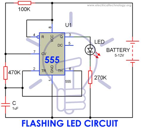
555 Timer-Based Flasher Circuit
The 555 timer is a popular integrated circuit that can be used to create a reliable and customizable flasher circuit. The 555 timer has three operating modes: astable, monostable, and bistable. For a flasher circuit, we’ll use the astable mode, which generates a continuous square wave output.
Here’s a 555 timer-based flasher circuit diagram:
                  +-----+
                  |     |
                  |     |
                  |  8  |
   +-----+        |     |       +-----+
   |     |  4  +--+-----+--+    |     |
   |     +-----+  7     6  +----|     |
   |           |           |    | 555 |
 +---+         |     5     |    |     |
 |   |         +-+-------+-+    |     |
 |C1 |         |           |    |     |
 +---+         |           |    |     |
   |           |  GND  +--|    |     |
   |           |  |  | |  |    |     |
  GND          |  |  | |  |    |     |
            R1 |  |  | |  |    |     |
+---\/\/\---+  |  |  | |  |    |     |
|           |  |  |  | |  |    |     |
|           +--+  |  | |  +----|     |
|               R2|  | |       |     |
|           +--\/\/\---+       +--+--+
|    LED    |     3  |            |
+----\/\/\--+        +------------+ DISCHARGE
|         1 |        |            | (Pin 7)
|           +--\/\/\-+            |
+----------------------+----------+
                       |
                      GND
In this diagram:
– R1 and R2 are resistors that control the charging and discharging of C1, determining the flashing rate.
– C1 is a capacitor that stores and releases electrical energy.
– The 555 timer is configured in astable mode, with pins 2 (TRIGGER) and 6 (THRESHOLD) connected.
– Pin 3 (OUTPUT) is connected to the LED through a current-limiting resistor.
– Pin 4 (RESET) is connected to the positive power supply to enable the timer.
– Pin 7 (DISCHARGE) is connected to the junction of R2 and C1.
The flashing rate can be calculated using the following formula:
f = 1.44 / ((R1 + 2 * R2) * C1)
Where:
– f is the flashing frequency in Hz
– R1 and R2 are the resistor values in ohms
– C1 is the capacitor value in farads
By adjusting the values of R1, R2, and C1, you can achieve the desired flashing rate for your application.
Microcontroller-Based Flasher Circuit
For more advanced projects that require precise control over the flashing pattern, a microcontroller-based flasher circuit can be used. Microcontrollers, such as Arduino or PIC, offer programmable control over the flashing sequence, allowing you to create complex patterns and respond to external inputs.
Here’s a simple Arduino-based flasher circuit diagram:
          +-----+
          |     |
          |     |
          |     |
        +-+-----+-+
        |         |
        |   USB   |
        |         |
     +--+----+----+--+
     |       |       |
     |     Arduino   |
     |               |
     |               |
     |          D13  |----+
     |               |    |
     |               |    |
     |               |    +---\/\/\----+-----+
     |               |    |           |     |
     |               |   LED       +-----+  |
     |               |                      |
     |  GND          |                     GND
     +---------------+----------------------+
In this diagram:
– The Arduino board is powered through the USB connection.
– The LED is connected to digital pin 13 (D13) through a current-limiting resistor.
To control the flashing, you’ll need to write a simple Arduino sketch that turns the LED on and off at the desired interval. Here’s an example sketch:
void setup() {
  pinMode(13, OUTPUT);
}

void loop() {
  digitalWrite(13, HIGH);
  delay(1000);
  digitalWrite(13, LOW);
  delay(1000);
}
This sketch sets pin 13 as an output and alternately turns the LED on and off with a 1-second delay between each state. You can modify the delay values to change the flashing rate or create more complex patterns using conditional statements and loops.

Flasher Circuit Applications
Flasher circuits have numerous applications across various fields, such as:
-
Automotive: Used in turn signals, hazard lights, and brake lights to indicate the vehicle’s intentions to other drivers.
-
Safety equipment: Employed in warning lights, beacons, and strobes to alert people of potential hazards or emergencies.
-
Toys and decorations: Creates attractive lighting effects in toys, holiday decorations, and novelty items.
-
Industrial machinery: Provides visual indicators for machine status, alarms, and process control.
-
Telecommunications: Used in network equipment to indicate the status of connections, data transfer, and power.
By understanding the principles behind flasher circuits and their various designs, you can adapt them to suit your specific application requirements.
Frequently Asked Questions (FAQ)
-
What is the purpose of a flasher circuit?
A flasher circuit is designed to create a periodic on-and-off effect, typically for visual indication or attention-grabbing purposes. It is used in applications such as indicator lights, warning signals, and decorative lighting. -
What components are necessary to build a basic flasher circuit?
To build a basic flasher circuit, you’ll need a power source, a resistor, a capacitor, a transistor (BJT or MOSFET), and an LED or lamp. These components work together to create the flashing effect. -
How can I adjust the flashing rate of a flasher circuit?
The flashing rate of a flasher circuit can be adjusted by changing the values of the resistors and capacitors in the circuit. Increasing the resistance or capacitance will slow down the flashing rate, while decreasing these values will speed it up. -
Can I use a flasher circuit with multiple LEDs?
Yes, you can use a flasher circuit with multiple LEDs by connecting them in parallel. However, make sure to use appropriate current-limiting resistors for each LED to prevent overloading the circuit. -
Are there any integrated circuits designed specifically for flasher circuits?
Yes, there are integrated circuits, such as the 555 timer, that are commonly used in flasher circuits. These ICs simplify the design process and provide stable, reliable performance.
Conclusion
Flasher circuits are essential components in many electronic projects, providing visual indication and attention-grabbing effects. By understanding the basic principles and components of flasher circuits, you can design and build your own circuits for various applications.
This comprehensive guide has covered the fundamentals of flasher circuits, including their components, working principles, and common designs. We’ve also explored advanced topics, such as 555 timer-based and microcontroller-based flasher circuits, which offer more flexibility and control over the flashing sequence.
Armed with this knowledge, you can now confidently create your own flasher circuit diagrams and adapt them to suit your specific needs. Whether you’re working on an automotive project, designing safety equipment, or creating eye-catching decorative lighting, the versatility of flasher circuits makes them an indispensable tool in your electronics toolkit.
No responses yet