Introduction to Adders in Digital Electronics
Adders are fundamental building blocks in digital electronics that perform the arithmetic operation of addition. They are essential components in various digital circuits, including arithmetic logic units (ALUs), microprocessors, and digital signal processing systems. Adders come in different types, with the two most basic being the half adder and the full adder. In this article, we will explore the key features, differences, and applications of full adders and half adders.
Understanding the Half Adder
Definition and Truth Table
A half adder is a digital circuit that performs the addition of two single-bit binary numbers (A and B) and produces two outputs: the sum (S) and the carry (C). The truth table for a half adder is as follows:
| A | B | S | C |
|---|---|---|---|
| 0 | 0 | 0 | 0 |
| 0 | 1 | 1 | 0 |
| 1 | 0 | 1 | 0 |
| 1 | 1 | 0 | 1 |
Logic Gates and Circuit Diagram
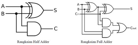
A half adder can be implemented using two basic logic gates: an XOR gate for the sum and an AND gate for the carry. The circuit diagram for a half adder is shown below:
       ___
A -----|   \
       | XOR>---- S
B -----|___/

       ___
A -----|   \
       | AND>---- C
B -----|___/
Limitations of Half Adders
While half adders are simple and efficient for adding two single-bit numbers, they have a significant limitation: they cannot handle the carry input from a previous addition operation. This means that half adders alone are not sufficient for adding multi-bit numbers or performing cascade addition, where the carry output from one adder is fed as the carry input to the next adder.

Exploring the Full Adder
Definition and Truth Table
A full adder is a digital circuit that performs the addition of three single-bit binary numbers: two operands (A and B) and a carry input (Cin) from a previous addition. It produces two outputs: the sum (S) and the carry output (Cout). The truth table for a full adder is as follows:
| A | B | Cin | S | Cout |
|---|---|---|---|---|
| 0 | 0 | 0 | 0 | 0 |
| 0 | 0 | 1 | 1 | 0 |
| 0 | 1 | 0 | 1 | 0 |
| 0 | 1 | 1 | 0 | 1 |
| 1 | 0 | 0 | 1 | 0 |
| 1 | 0 | 1 | 0 | 1 |
| 1 | 1 | 0 | 0 | 1 |
| 1 | 1 | 1 | 1 | 1 |
Logic Gates and Circuit Diagram
A full adder can be implemented using several logic gates, including XOR, AND, and OR gates. One common implementation of a full adder uses two half adders and an OR gate, as shown in the circuit diagram below:
       ___
A -----|   \
       | XOR>----
B -----|___/     |
                 |    ___
C<sub>in</sub> --|---|   \
                 |   | XOR>---- S
                 |---|___/
                 |
                 |    ___
                 |---|   \
                 |   | AND>----
                 |---|___/     |
                 |             |    ___
                 |-------------|---|   \
                               |   | OR >---- C<sub>out</sub>
                               |---|___/
                               |
                               |    ___
                               |---|   \
                               |   | AND>----
                               |---|___/
Advantages of Full Adders
Full adders overcome the limitations of half adders by incorporating the carry input from a previous addition operation. This allows full adders to be cascaded together to perform multi-bit addition. By connecting multiple full adders in series, with the carry output of one adder serving as the carry input to the next, we can create a ripple carry adder capable of adding numbers with any number of bits.

Ripple Carry Adder and Its Applications
Cascading Full Adders for Multi-bit Addition
A ripple carry adder is a digital circuit that consists of multiple full adders connected in series to perform multi-bit addition. In a ripple carry adder, the carry output of each full adder is connected to the carry input of the next full adder, creating a ripple effect as the carry propagates from the least significant bit (LSB) to the most significant bit (MSB).
The block diagram of a 4-bit ripple carry adder is shown below:
    A3 B3     A2 B2     A1 B1     A0 B0
     |  |      |  |      |  |      |  |
   __|__|__  __|__|__  __|__|__  __|__|__
  |        ||        ||        ||        |
  | Full   || Full   || Full   || Full   |
  | Adder  || Adder  || Adder  || Adder  |
  |________||________||________||________|
     |  |      |  |      |  |      |  |
    C<sub>out</sub>    C3       C2       C1       C0
     |
    S3        S2        S1        S0
Applications of Ripple Carry Adders
Ripple carry adders are widely used in various digital systems and applications, such as:
-
Arithmetic Logic Units (ALUs): ALUs are essential components of processors that perform arithmetic and logical operations. Ripple carry adders are often used within ALUs to perform addition operations.
-
Microprocessors: Microprocessors rely on adders to perform arithmetic calculations. Ripple carry adders are commonly used in the arithmetic units of microprocessors due to their simplicity and efficiency for small-scale additions.
-
Digital Signal Processing (DSP): DSP algorithms often require the addition of multi-bit numbers. Ripple carry adders are employed in DSP systems to perform these addition operations.
-
Embedded Systems: Embedded systems, such as microcontrollers and system-on-chip (SoC) devices, incorporate adders for various arithmetic computations. Ripple carry adders are frequently used in these systems due to their compact size and low power consumption.

Comparison of Full Adder and Half Adder
Key Differences
The main differences between a full adder and a half adder are:
-
Number of Inputs: A half adder has two single-bit inputs (A and B), while a full adder has three inputs: two single-bit operands (A and B) and a carry input (Cin) from a previous addition.
-
Carry Handling: A half adder does not have a carry input and cannot handle the carry from a previous addition operation. In contrast, a full adder includes a carry input, allowing it to handle the carry from a previous addition and making it suitable for multi-bit addition.
-
Complexity: A half adder is simpler in design and requires fewer logic gates compared to a full adder. A half adder can be implemented using only an XOR gate and an AND gate, while a full adder typically requires multiple logic gates, such as XOR, AND, and OR gates.
Choosing Between Full Adder and Half Adder
The choice between using a full adder or a half adder depends on the specific requirements of the digital system or application:
-
Single-bit Addition: If the system only needs to perform single-bit addition without handling carry, a half adder is sufficient and provides a simpler and more compact solution.
-
Multi-bit Addition: When the system requires the addition of multi-bit numbers or needs to handle carry propagation, a full adder is necessary. Full adders can be cascaded together to form ripple carry adders for adding numbers with any number of bits.
-
Cascading and Scalability: Full adders are designed to be cascaded together to create larger adders, such as ripple carry adders. They provide better scalability and flexibility for building adders with a higher number of bits. Half adders, on the other hand, are not suitable for cascading and are limited to single-bit additions.
Frequently Asked Questions (FAQ)
-
What is the main difference between a half adder and a full adder?
The main difference between a half adder and a full adder is that a half adder has only two single-bit inputs and does not handle carry, while a full adder has three inputs (two operands and a carry input) and can handle the carry from a previous addition. -
Can half adders be used for multi-bit addition?
No, half adders cannot be used for multi-bit addition because they do not have a carry input and cannot handle the carry from a previous addition operation. For multi-bit addition, full adders are required. -
How are full adders cascaded together to create a ripple carry adder?
Full adders are cascaded together by connecting the carry output of one adder to the carry input of the next adder. This creates a ripple effect as the carry propagates from the least significant bit to the most significant bit, allowing the addition of multi-bit numbers. -
What are some common applications of ripple carry adders?
Ripple carry adders are commonly used in various digital systems and applications, such as arithmetic logic units (ALUs), microprocessors, digital signal processing (DSP) systems, and embedded systems, where multi-bit addition is required. -
Can a full adder be implemented using half adders?
Yes, a full adder can be implemented using two half adders and an additional OR gate. The first half adder adds the two operands (A and B), while the second half adder adds the sum from the first half adder with the carry input. The carry outputs from both half adders are then combined using an OR gate to generate the final carry output of the full adder.
Conclusion
Full adders and half adders are fundamental building blocks in digital electronics, each with its own key features and applications. Half adders are simpler circuits that perform single-bit addition without handling carry, while full adders are more complex circuits that can handle the carry input from a previous addition and are suitable for multi-bit addition.
Ripple carry adders, constructed by cascading multiple full adders, are widely used in various digital systems and applications that require multi-bit addition, such as arithmetic logic units, microprocessors, digital signal processing systems, and embedded systems.
Understanding the differences between full adders and half adders, as well as their applications, is crucial for designing efficient and effective digital circuits. By selecting the appropriate adder based on the specific requirements of the system, designers can optimize performance, minimize complexity, and ensure the correct functionality of the digital circuit.
No responses yet