Table of Contents
- Introduction to Induction Heating
- Components of an Induction Heater Circuit
- Designing the Induction Heater Circuit
- Determining Power Requirements
- Selecting the IGBT
- Designing the Resonant Tank Circuit
- Designing the Gate Drive Circuit
- Designing the Power Supply
- Building the Induction Heater Circuit
- PCB Design and Fabrication
- Component Selection and Sourcing
- Assembly and Testing
- Safety Considerations
- Applications of Induction Heating
- Frequently Asked Questions (FAQ)
- Conclusion
Introduction to Induction Heating
Induction heating relies on the principle of electromagnetic induction, discovered by Michael Faraday in 1831. When an alternating current (AC) flows through a coil, it generates a fluctuating magnetic field. If an electrically conductive object is placed within this magnetic field, eddy currents are induced within the object. These eddy currents flow against the electrical resistivity of the material, generating heat through Joule heating.
The amount of heat generated depends on several factors:
– The strength of the magnetic field
– The frequency of the alternating current
– The electrical resistivity of the object
– The magnetic permeability of the object
Induction heating offers several advantages over other heating methods:
– Rapid heating: Induction can heat objects very quickly due to the direct generation of heat within the object.
– Precision: By controlling the strength and frequency of the magnetic field, the heating can be precisely targeted and controlled.
– Safety: Since the heating occurs within the object itself, the surrounding area remains cooler, reducing the risk of burns or fires.
– Efficiency: Induction heating is highly efficient, as the heat is generated directly within the object rather than being transferred from an external source.

Components of an Induction Heater Circuit
A typical induction heater circuit consists of the following main components:
-
High-frequency power inverter: This converts low-frequency (50/60 Hz) AC power into high-frequency (tens to hundreds of kHz) AC power. The most common inverter topology for induction heating is the half-bridge or full-bridge resonant inverter, using power electronic switches like IGBTs or MOSFETs.
-
Resonant tank circuit: This consists of the induction heating coil (work coil) and a capacitor bank, forming a resonant LC circuit. The resonant frequency of this circuit is tuned to match the switching frequency of the inverter for maximum power transfer.
-
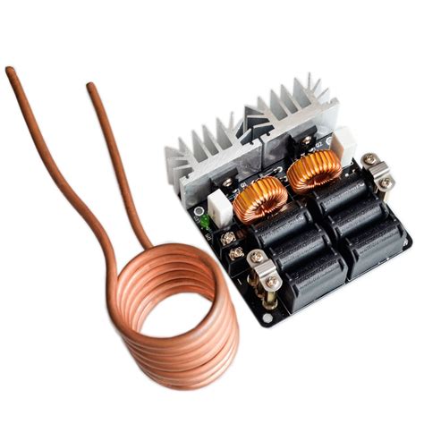
Induction heating coil: This is a coil of copper wire or tubing that generates the magnetic field for heating the workpiece. The coil geometry and number of turns are designed based on the size, shape, and material properties of the workpiece.
-
Workpiece: This is the electrically conductive object to be heated, such as a metal part or a cooking vessel. The workpiece is placed inside or in close proximity to the induction heating coil.
-
Gate drive circuit: This provides the necessary driving signals for the power electronic switches in the inverter, ensuring proper switching timing and protection.
-
Power supply: This provides the necessary DC power for the inverter and gate drive circuits. It typically includes rectification, filtering, and voltage regulation stages.
-
Cooling system: Depending on the power level and application, the induction heater may require cooling for the power electronic components, the induction coil, and/or the workpiece. This can be achieved through forced air, water, or oil cooling.
-
Control and monitoring system: This includes sensors, feedback circuits, and a microcontroller or dedicated control IC for regulating the output power, frequency, and other parameters of the induction heater based on user settings and system conditions.

Designing the Induction Heater Circuit
Determining Power Requirements
The first step in designing an induction heater is to determine the power requirements based on the intended application and workpiece. The required power depends on factors such as:
– The size and shape of the workpiece
– The desired heating rate and final temperature
– The material properties (electrical resistivity, magnetic permeability, specific heat capacity) of the workpiece
– The coupling efficiency between the coil and the workpiece
For example, for a small-scale induction heater for heating metal parts, a power output of 1-2 kW may be sufficient. For larger industrial applications like metal melting or forging, power levels can range from tens to hundreds of kilowatts.
Selecting the IGBT
The choice of power electronic switch is critical for the performance and reliability of the induction heater. Insulated-Gate Bipolar Transistors (IGBTs) are commonly used for high-power induction heating applications due to their high voltage and current ratings, fast switching speeds, and low conduction losses.
When selecting an IGBT, consider the following parameters:
– Voltage rating: The IGBT must be able to withstand the maximum voltage across it, which is typically determined by the DC bus voltage of the inverter.
– Current rating: The IGBT must be able to handle the peak and RMS currents flowing through it, based on the output power and duty cycle of the inverter.
– Switching frequency: The IGBT must be capable of switching at the desired operating frequency of the inverter, which is typically in the range of tens to hundreds of kHz for induction heating.
– Power dissipation: The IGBT package and cooling system must be designed to handle the expected power losses, which include conduction losses and switching losses.
Some popular IGBT modules for induction heating applications include the Infineon EconoPACK™ and EconoDUAL™ series, the Mitsubishi Electric IGBT modules, and the Semikron SKiiP and SEMITRANS modules.
Designing the Resonant Tank Circuit
The resonant tank circuit, consisting of the induction heating coil and a capacitor bank, is the heart of the induction heater. Its design is critical for achieving efficient power transfer and heating performance.
The resonant frequency of the tank circuit should be tuned to match the switching frequency of the inverter. This is achieved by selecting the appropriate inductance of the coil and capacitance of the capacitor bank, based on the formula:
f = 1 / (2π√(LC))
where:
– f is the resonant frequency (Hz)
– L is the inductance of the coil (H)
– C is the capacitance of the capacitor bank (F)
The inductance of the coil depends on its geometry (diameter, number of turns, length) and the magnetic permeability of the workpiece. It can be calculated using formulas or finite element analysis (FEA) simulations.
The capacitor bank is typically made up of high-frequency, high-voltage polypropylene film capacitors connected in series and/or parallel to achieve the required capacitance and voltage rating. The capacitors must be able to handle the high RMS currents and temperatures generated in the resonant circuit.
Designing the Gate Drive Circuit
The gate drive circuit provides the necessary driving signals for the IGBTs in the inverter, ensuring proper switching timing and protection. A well-designed gate drive circuit should provide:
– Sufficient gate voltage and current to fully turn on and off the IGBTs
– Fast rise and fall times for the gate signals to minimize switching losses
– Galvanic isolation between the control and power circuits, typically using optocouplers or pulse transformers
– Protection features such as short-circuit detection, overcurrent limiting, and soft shut-down
There are several gate drive IC options available, such as the Infineon EiceDRIVER™ family, the Texas Instruments UCC27531 and UCC21520 drivers, and the Analog Devices ADuM4223 isolated gate driver.
Designing the Power Supply
The power supply provides the necessary DC power for the inverter and gate drive circuits. It typically includes the following stages:
1. Rectification: Converting the input AC voltage to DC using a bridge rectifier or active front-end rectifier.
2. Filtering: Smoothing the rectified DC voltage using capacitors and/or inductors to reduce voltage ripple.
3. Voltage regulation: Maintaining a stable DC bus voltage using a voltage regulator or DC-DC converter.
The power supply should be designed to handle the expected power draw of the induction heater, with sufficient margin for transient loads and fault conditions. It should also include protection features such as input fuses, surge suppressors, and overvoltage/undervoltage lockout.

Building the Induction Heater Circuit
PCB Design and Fabrication
The induction heater circuit is typically built on a printed circuit board (PCB) for reliability and ease of assembly. The PCB should be designed with consideration for:
– High-current traces and planes for the power components
– Proper grounding and shielding to minimize EMI and noise
– Adequate clearances and creepage distances for high-voltage isolation
– Thermal management, including heatsinks and cooling fans
The PCB can be designed using EDA software such as Altium Designer, KiCad, or Eagle, and fabricated by a PCB manufacturer.
Component Selection and Sourcing
The components for the induction heater circuit should be selected based on the design requirements and specifications. This includes the IGBTs, capacitors, inductors, gate drive ICs, power supply components, and sensors.
When sourcing components, consider factors such as:
– Voltage and current ratings
– Thermal performance and packaging
– Availability and lead times
– Cost and minimum order quantities
Some popular component distributors for power electronic components include Digi-Key, Mouser Electronics, and Newark Electronics.
Assembly and Testing
The induction heater circuit should be assembled on the PCB according to the schematic and layout designs. This includes soldering the components, attaching heatsinks and cooling fans, and making any necessary wiring connections.
Before powering up the circuit, perform a thorough visual inspection and continuity check to ensure proper assembly and catch any potential errors.
Testing and debugging the induction heater circuit involves:
– Verifying the DC bus voltage and current
– Measuring the gate drive signals and IGBT switching waveforms
– Tuning the resonant tank circuit for maximum power transfer
– Monitoring the system temperatures and implementing thermal protection if necessary
– Conducting load tests with the intended workpiece and verifying the heating performance
Safety Considerations
Induction heating circuits involve high voltages, high currents, and strong magnetic fields, which can pose safety hazards if not properly designed and handled. Some key safety considerations include:
- Proper high-voltage insulation and isolation
- Grounding and shielding to prevent electric shock and EMI
- Overcurrent, overvoltage, and thermal protection
- Proper enclosure and guarding to prevent access to live parts
- Warning labels and user training on safe operation and maintenance
Always follow relevant electrical safety standards and regulations, such as UL, IEC, and NFPA 70E, when designing and working with induction heating circuits.
Applications of Induction Heating
Induction heating has a wide range of applications across various industries, including:
- Metal processing: Melting, forging, welding, brazing, hardening, and annealing of metals
- Cooking: Induction cooktops and ovens for residential and commercial kitchens
- Automotive: Induction heating for shrink fitting, curing adhesives, and manufacturing parts
- Medical: Induction heating for sterilization, hyperthermia treatment, and dental tools
- Plastics: Induction heating for welding, forming, and curing of plastic materials
- Semiconductor: Induction heating for crystal growth, wafer processing, and packaging
- Aerospace: Induction heating for repairing and manufacturing aircraft components
- Home appliances: Induction heating for clothes drying, water heating, and space heating
Each application may have specific requirements for power level, frequency, coil design, and control, but the basic principles of induction heating remain the same.
Frequently Asked Questions (FAQ)
- What materials can be heated with induction heating?
-
Induction heating can be used to heat electrically conductive materials, such as metals (steel, aluminum, copper, brass), graphite, and some conductive composites. The material must have sufficient electrical conductivity and magnetic permeability to generate eddy currents and heat up efficiently.
-
Can induction heating be used for non-conductive materials?
-
Induction heating does not work directly on non-conductive materials like plastics, glass, or ceramics. However, it is possible to indirectly heat non-conductive materials by using a conductive susceptor (e.g., a metal plate or mesh) that is heated by induction and then transfers the heat to the non-conductive material through conduction or radiation.
-
How does the frequency of the magnetic field affect induction heating?
-
The frequency of the magnetic field determines the depth of penetration of the induced eddy currents in the workpiece. Higher frequencies result in shallower penetration and more localized heating, while lower frequencies penetrate deeper and provide more uniform heating. The optimal frequency depends on the size, shape, and material properties of the workpiece.
-
What are the advantages of induction heating over other heating methods?
-
Induction heating offers several advantages, including:
- Rapid and precise heating
- High energy efficiency (up to 90%)
- No direct contact between the heating source and the workpiece
- Reduced risk of contamination or damage to the workpiece
- Compact and portable equipment
- Easy automation and control
-
What are some challenges in designing and operating induction heating systems?
- Some challenges in induction heating include:
- Ensuring proper impedance matching between the power supply, coil, and workpiece for maximum efficiency
- Managing heat transfer and thermal stresses in the workpiece and coil
- Minimizing electromagnetic interference (EMI) and complying with EMC regulations
- Ensuring operator safety and preventing exposure to high voltages, currents, and magnetic fields
- Optimizing the coil design and positioning for specific workpiece geometries and materials
Conclusion
Induction heating is a powerful and versatile technology with numerous applications in industry, medicine, and household appliances. By understanding the principles of electromagnetic induction and resonant circuits, designers can create efficient and effective induction heating systems for a wide range of uses.
This article has provided a comprehensive guide on how to design and build an induction heater circuit, including the key components, design considerations, and practical steps for assembly and testing. By following these guidelines and best practices, readers can successfully develop their own induction heating solutions for various applications.
However, it is important to approach induction heating with caution and respect for the potential hazards involved. Always prioritize safety by following proper design, construction, and operation procedures, and complying with relevant standards and regulations.
With the right knowledge, skills, and precautions, induction heating can be a valuable tool for heating, melting, welding, and processing a wide range of materials efficiently and effectively.
No responses yet