What is the MCP3008?
The MCP3008 is an 8-channel, 10-bit analog-to-digital converter manufactured by Microchip Technology. It is designed to provide a simple interface between analog sensors and digital systems, allowing you to measure and process analog signals with ease. The chip uses the SPI (Serial Peripheral Interface) protocol for communication, making it compatible with a wide range of microcontrollers and single-board computers, such as Arduino, Raspberry Pi, and PIC.
Key Features of the MCP3008
- 8 analog input channels
- 10-bit resolution (1024 discrete output values)
- SPI interface for easy communication with microcontrollers
- Low power consumption: 5 nA typical standby current, 400 µA maximum active current
- Wide operating voltage range: 2.7V to 5.5V
- Small package size: 16-pin PDIP, SOIC, or TSSOP
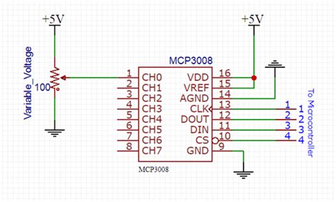
MCP3008 Pinout and Pin Description
To effectively use the MCP3008, it is essential to understand its pinout and the function of each pin. The following table and diagram provide a detailed overview of the MCP3008 pinout:
| Pin Number | Pin Name | Description |
|---|---|---|
| 1 | CH0 | Analog Input Channel 0 |
| 2 | CH1 | Analog Input Channel 1 |
| 3 | CH2 | Analog Input Channel 2 |
| 4 | CH3 | Analog Input Channel 3 |
| 5 | CH4 | Analog Input Channel 4 |
| 6 | CH5 | Analog Input Channel 5 |
| 7 | CH6 | Analog Input Channel 6 |
| 8 | CH7 | Analog Input Channel 7 |
| 9 | DGND | Digital Ground |
| 10 | CS/SHDN | Chip Select/Shutdown Input |
| 11 | DIN | Serial Data Input |
| 12 | DOUT | Serial Data Output |
| 13 | CLK | Serial Clock Input |
| 14 | AGND | Analog Ground |
| 15 | VREF | Reference Voltage Input |
| 16 | VDD | Power Supply (2.7V to 5.5V) |
Analog Input Channels (CH0-CH7)
The MCP3008 features eight analog input channels, labeled CH0 through CH7. These channels allow you to connect up to eight different analog sensors or signals to the ADC. The analog voltage on each channel is converted to a corresponding 10-bit digital value.
Digital and Analog Ground (DGND and AGND)
The MCP3008 has separate ground pins for digital and analog signals. DGND (pin 9) is the digital ground, which should be connected to the ground of the microcontroller or digital system. AGND (pin 14) is the analog ground, which should be connected to the ground of the analog sensors or signals. Keeping the digital and analog grounds separate helps to minimize noise and interference.
Chip Select/Shutdown Input (CS/SHDN)
The CS/SHDN pin (pin 10) serves two purposes:
-
Chip Select: When CS is low, the MCP3008 is selected and ready for communication. When CS is high, the device is deselected and ignores incoming data.
-
Shutdown: When CS is held low for more than 100 ns, the MCP3008 enters shutdown mode, reducing its power consumption to less than 5 nA. To exit shutdown mode, bring CS back high.
Serial Data Input (DIN) and Output (DOUT)
DIN (pin 11) is the serial data input pin, used to send configuration data and channel selection information from the microcontroller to the MCP3008. DOUT (pin 12) is the serial data output pin, used to send the converted digital values from the MCP3008 to the microcontroller.
Serial Clock Input (CLK)
The CLK pin (pin 13) is the serial clock input, used to synchronize the data transfer between the microcontroller and the MCP3008. The maximum clock frequency is 3.6 MHz when VDD is 5V, and 1.35 MHz when VDD is 2.7V.
Reference Voltage Input (VREF)
VREF (pin 15) is the reference voltage input pin. The voltage applied to this pin determines the input range of the analog channels. By default, if VREF is left unconnected, it is internally tied to VDD, resulting in an input range of 0V to VDD. You can connect an external voltage reference to VREF to set a different input range, such as 0V to 3.3V or 0V to 2.5V.
Power Supply (VDD)
VDD (pin 16) is the power supply pin for the MCP3008. The chip can operate with a supply voltage ranging from 2.7V to 5.5V. It is important to ensure that the supply voltage is stable and within the specified range for accurate analog-to-digital conversions.

Communicating with the MCP3008 using SPI
The MCP3008 uses the Serial Peripheral Interface (SPI) protocol for communication with a microcontroller or digital system. SPI is a synchronous, full-duplex communication protocol that requires four signals:
- MOSI (Master Out, Slave In): Data signal from the microcontroller to the MCP3008.
- MISO (Master In, Slave Out): Data signal from the MCP3008 to the microcontroller.
- SCK (Serial Clock): Clock signal generated by the microcontroller to synchronize data transfer.
- CS (Chip Select): Signal used to select the MCP3008 for communication.
To initiate a conversion and read the digital value from the MCP3008, follow these steps:
- Set the CS pin low to select the MCP3008.
- Send a 3-bit start sequence (000) followed by a 4-bit channel selection via the MOSI pin.
- Send a null bit (0) to initiate the conversion.
- Wait for the conversion to complete (maximum conversion time is 1.6 µs at VDD = 5V, 3.2 µs at VDD = 2.7V).
- Read the 10-bit digital value (MSB first) from the MISO pin.
- Set the CS pin high to deselect the MCP3008.
The following timing diagram illustrates the SPI communication sequence for a single channel conversion:
       Start   Single-Ended Channel Selection                          Null          MSB                                   LSB
CS   --+       +----+----+----+----+----+----+----+----+                +            +----+----+----+----+----+----+----+----+----+----+
       |       |    |    |    |    |    |    |    |    |                |            |    |    |    |    |    |    |    |    |    |    |
MOSI   +-------+----+----+----+----+----+----+----+----+----------------+------------+----+----+----+----+----+----+----+----+----+----+
         000     S2   S1   S0   X    X    X    X    X                    0
                +----+----+----+----+----+----+----+----+                +            +----+----+----+----+----+----+----+----+----+----+
MISO            |    |    |    |    |    |    |    |    |                |            | D9 | D8 | D7 | D6 | D5 | D4 | D3 | D2 | D1 | D0 |
                +----+----+----+----+----+----+----+----+----------------+------------+----+----+----+----+----+----+----+----+----+----+

SCK   --+----+----+----+----+----+----+----+----+----+----+----+----+----+----+----+----+----+----+----+----+----+----+----+----+----+----+
         1    2    3    4    5    6    7    8    9    10   11   12   13   14   15   16   17   18   19   20   21   22   23   24
In this diagram:
– CS is the Chip Select signal
– MOSI is the data sent from the microcontroller to the MCP3008
– MISO is the data sent from the MCP3008 to the microcontroller
– SCK is the Serial Clock signal
– S2, S1, and S0 represent the channel selection bits
– X represents “don’t care” bits
– D9 through D0 represent the 10-bit digital output value
By following this communication sequence, you can read the analog values from the selected channel on the MCP3008.

Connecting the MCP3008 to a Microcontroller
To connect the MCP3008 to a microcontroller, such as an Arduino or Raspberry Pi, follow these steps:
- Connect the VDD pin to the microcontroller’s power supply (e.g., 5V or 3.3V).
- Connect the DGND and AGND pins to the microcontroller’s ground.
- Connect the CLK pin to the microcontroller’s SPI clock pin (e.g., SCK on Arduino, SCLK on Raspberry Pi).
- Connect the DIN pin to the microcontroller’s SPI MOSI pin (e.g., MOSI on Arduino, MOSI on Raspberry Pi).
- Connect the DOUT pin to the microcontroller’s SPI MISO pin (e.g., MISO on Arduino, MISO on Raspberry Pi).
- Connect the CS/SHDN pin to a digital output pin on the microcontroller for chip selection.
- If using an external voltage reference, connect it to the VREF pin; otherwise, leave VREF unconnected.
Here’s an example connection diagram for an Arduino Uno:
MCP3008     Arduino Uno
--------------------------
VDD         5V
VREF        5V (or external reference)
AGND        GND
CLK         SCK (D13)
DIN         MOSI (D11)
DOUT        MISO (D12)
CS/SHDN     D10 (or any digital pin)
DGND        GND
CH0-CH7     Analog sensors or signals

Sample Code for Reading Analog Values
Here’s a simple Arduino sketch that demonstrates how to read analog values from the MCP3008:
#include <SPI.h>

const int CS_PIN = 10;

void setup() {
  pinMode(CS_PIN, OUTPUT);
  digitalWrite(CS_PIN, HIGH);

  SPI.begin();
  Serial.begin(9600);
}

void loop() {
  for (int channel = 0; channel < 8; channel++) {
    int value = readMCP3008(channel);
    Serial.print("Channel ");
    Serial.print(channel);
    Serial.print(": ");
    Serial.println(value);
  }
  delay(1000);
}

int readMCP3008(int channel) {
  digitalWrite(CS_PIN, LOW);

  SPI.transfer(0b00000001); // Start bit
  int highByte = SPI.transfer((channel & 0b0111) << 4);
  int lowByte = SPI.transfer(0);

  digitalWrite(CS_PIN, HIGH);

  return ((highByte & 0x03) << 8) | lowByte;
}
This sketch reads the analog values from all eight channels of the MCP3008 and prints them to the Serial Monitor every second. The readMCP3008 function handles the SPI communication and returns the 10-bit digital value for the selected channel.
Applications and Projects using the MCP3008
The MCP3008 is a versatile ADC that can be used in a wide range of applications and projects. Some examples include:
- Temperature monitoring using thermistors or temperature sensors (e.g., LM35, TMP36)
- Light intensity measurement using photoresistors or phototransistors
- Soil moisture sensing for plant watering systems
- Pressure sensing using pressure sensors (e.g., MPX4115A)
- Analog joystick or potentiometer input for gaming or control applications
- Battery voltage monitoring
- Gas detection using analog gas sensors (e.g., MQ series)
- Audio signal processing and visualization
By combining the MCP3008 with various analog sensors and a microcontroller, you can create powerful and efficient data acquisition and control systems.
Troubleshooting Common Issues
- Incorrect readings or noise:
- Ensure that the analog and digital grounds are connected properly and separately.
- Use decoupling capacitors (0.1 µF ceramic) between VDD and GND, close to the MCP3008.
- Keep the wiring between the analog sensors and the MCP3008 as short as possible.
-
Use shielded cables for analog signals in noisy environments.
-
SPI communication problems:
- Double-check the connections between the microcontroller and the MCP3008.
- Ensure that the SPI library is initialized correctly and the proper pins are used.
-
Verify that the CS pin is toggled correctly during communication.
-
Incorrect channel selection:
- Make sure that the channel selection bits are set correctly in the SPI transfer sequence.
-
Double-check the wiring between the analog sensors and the MCP3008 channels.
-
Inaccurate readings due to incorrect reference voltage:
- If using an external reference voltage, ensure that it is stable and within the specified range.
- Verify that the VREF pin is connected to the desired reference voltage or left unconnected for VDD reference.
By carefully checking the connections, wiring, and code, most issues with the MCP3008 can be resolved quickly.
Frequently Asked Questions (FAQ)
- What is the difference between the MCP3008 and MCP3004?
-
The MCP3008 has 8 analog input channels, while the MCP3004 has only 4 channels. Otherwise, they have the same functionality and pinout.
-
Can I use the MCP3008 with a 3.3V microcontroller?
-
Yes, the MCP3008 is compatible with both 3.3V and 5V microcontrollers. Just make sure to connect the VDD pin to the appropriate voltage level.
-
How do I set the analog input range for the MCP3008?
-
By default, the analog input range is 0V to VDD. To set a different range, connect the desired reference voltage to the VREF pin. For example, connecting VREF to 3.3V will result in an input range of 0V to 3.3V.
-
What is the maximum sampling rate of the MCP3008?
-
The maximum sampling rate depends on the clock frequency and the microcontroller’s processing speed. With a 5V supply and a 3.6 MHz clock, the maximum theoretical sampling rate is around 200 ksps (kilo-samples per second). However, practical limitations, such as microcontroller speed and SPI overhead, may lower this value.
-
Can I use multiple MCP3008s with a single microcontroller?
- Yes, you can connect multiple MCP3008s to a single microcontroller by using separate CS pins for each device. The other SPI pins (CLK, DIN, DOUT) can be shared among the devices.
Conclusion
The MCP3008 is a powerful and easy-to-use analog-to-digital converter that can greatly expand the capabilities of your microcontroller projects. By understanding the MCP3008 pinout, SPI communication, and connection process, you can easily integrate this versatile chip into your designs and create sophisticated data acquisition and control systems.
Remember to follow best practices, such as proper grounding, decoupling, and wiring, to ensure accurate and reliable readings from your analog sensors. With the MCP3008, you can unleash the full potential of your microcontroller and bring your projects to the next level.
No responses yet