Introduction to Micro Ampere Meters
A micro ampere meter, also known as a microammeter or μA meter, is an electrical measuring instrument used to measure very small electric currents, typically in the range of microamperes (μA). These meters are essential tools for troubleshooting, testing, and monitoring low-current electronic circuits and devices.
Micro ampere meters are widely used in various fields, including:
- Electronics
- Electrical engineering
- Scientific research
- Medical equipment
- Automotive industry
How Micro Ampere Meters Work
Basic Principle
Micro ampere meters work on the principle of measuring the voltage drop across a known low-value resistor (shunt) when a small current passes through it. According to Ohm’s law, the voltage drop across a resistor is directly proportional to the current flowing through it:
V = I × R
where:
– V is the voltage drop across the resistor (in volts)
– I is the current flowing through the resistor (in amperes)
– R is the resistance of the resistor (in ohms)
By measuring the voltage drop and knowing the value of the shunt resistor, the micro ampere meter can calculate the current flowing through the circuit.
Sensitivity and Range
The sensitivity of a micro ampere meter is determined by the value of the shunt resistor and the full-scale deflection (FSD) current of the meter movement. A typical micro ampere meter has a sensitivity of 50 μA or 100 μA, meaning that a current of 50 μA or 100 μA will cause the meter needle to deflect to its maximum scale value.
Micro ampere meters can have different measurement ranges, depending on the application and the expected current levels. Common ranges include:
| Range | Current |
|---|---|
| 0-50 μA | 0 to 50 microamperes |
| 0-100 μA | 0 to 100 microamperes |
| 0-500 μA | 0 to 500 microamperes |
| 0-1 mA | 0 to 1 milliampere |
To measure currents higher than the meter’s maximum range, external shunt resistors can be used to extend the measurement range.

Components of a Micro Ampere Meter
A typical micro ampere meter consists of the following components:
- Meter movement (D’Arsonval movement)
- Shunt resistor
- Scale and pointer
- Zero adjustment screw
- Terminals
Meter Movement (D’Arsonval Movement)
The heart of a micro ampere meter is the D’Arsonval movement, which consists of a permanent magnet, a moving coil, a pointer, and a spring. When a current passes through the moving coil, it generates a magnetic field that interacts with the permanent magnet, causing the coil and pointer to rotate. The spring provides a restoring force, ensuring that the pointer returns to its zero position when no current is flowing.
Shunt Resistor
The shunt resistor is a low-value, high-precision resistor connected in parallel with the meter movement. Its purpose is to divert most of the current away from the sensitive meter movement, allowing the meter to measure higher currents without damaging the movement.
The value of the shunt resistor is chosen based on the desired measurement range and the sensitivity of the meter movement. For example, if a meter movement has a sensitivity of 50 μA and a shunt resistor of 9,950 Ω is used, the meter will have a measurement range of 0-500 μA.
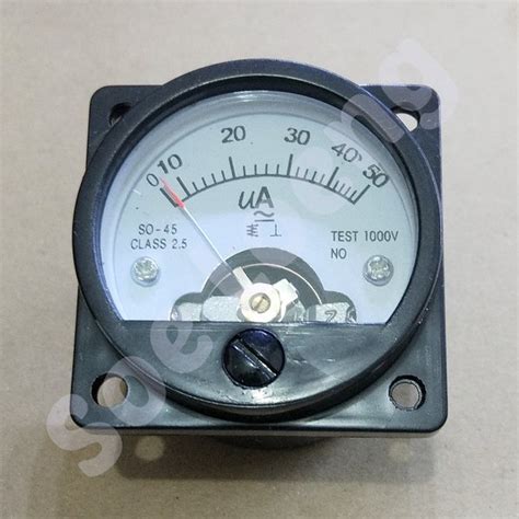
Scale and Pointer
The scale and pointer of a micro ampere meter provide a visual indication of the measured current. The scale is usually marked in microamperes or milliamperes, depending on the meter’s range. The pointer, attached to the moving coil, moves across the scale to indicate the current value.
Zero Adjustment Screw
The zero adjustment screw is used to calibrate the meter and ensure that the pointer rests at the zero mark when no current is flowing through the meter. This adjustment compensates for any mechanical or electrical imbalances in the meter movement.
Terminals
Micro ampere meters have two terminals, one for connecting the meter in series with the circuit under test and the other for connecting the shunt resistor (if external).

Micro Ampere Meter Circuit Diagram
A basic micro ampere meter circuit consists of the meter movement, shunt resistor, and terminals. The following diagram illustrates a typical micro ampere meter circuit:
       +-----------+
       |           |
       |  Meter    |
+------+  Movement +-----+
|      |           |     |
|      +-----------+     |
|                        |
|         Shunt          |
|        Resistor        |
|                        |
+------------------------+
In this diagram:
– The meter movement is represented by the rectangle labeled “Meter Movement”
– The shunt resistor is connected in parallel with the meter movement
– The terminals are shown as the two lines extending from the shunt resistor
To use the micro ampere meter, the circuit under test is connected in series with the meter terminals. The current flowing through the circuit will be divided between the meter movement and the shunt resistor, with the majority of the current flowing through the shunt resistor to protect the sensitive meter movement.

Applications of Micro Ampere Meters
Micro ampere meters find applications in various fields where low-current measurements are required. Some common applications include:
Electronics and Electrical Engineering
- Testing and troubleshooting electronic circuits
- Measuring leakage currents in capacitors and insulators
- Monitoring the performance of low-power devices, such as sensors and microcontrollers
Scientific Research
- Measuring ionic currents in electrochemical experiments
- Monitoring the output of photovoltaic cells and other energy harvesting devices
- Investigating the electrical properties of materials
Medical Equipment
- Monitoring the output of biosensors and medical diagnostic devices
- Measuring the currents in electrophysiology experiments
- Testing the performance of pacemakers and other implantable medical devices
Automotive Industry
- Testing the continuity and performance of electrical components, such as sensors and actuators
- Diagnosing faults in vehicle electrical systems
- Monitoring the charging and discharging currents of batteries
Selecting the Right Micro Ampere Meter
When choosing a micro ampere meter for a specific application, consider the following factors:
-
Measurement range: Ensure that the meter’s range covers the expected current levels in your application.
-
Accuracy and resolution: Choose a meter with sufficient accuracy and resolution for your needs. Typical micro ampere meters have an accuracy of ±1% to ±2% of full scale and a resolution of 0.5 μA to 1 μA.
-
Input impedance: The meter’s input impedance should be much higher than the impedance of the circuit under test to minimize loading effects and ensure accurate measurements.
-
Durability and reliability: Select a meter with a robust construction and reliable components to withstand the intended operating environment and provide long-term performance.
-
Additional features: Some micro ampere meters offer additional features, such as data logging, digital displays, or computer connectivity, which may be beneficial for your application.
Proper Use and Maintenance of Micro Ampere Meters
To ensure accurate measurements and prolong the life of your micro ampere meter, follow these guidelines:
-
Always connect the meter in series with the circuit under test, never in parallel.
-
Do not exceed the meter’s maximum current rating to avoid damaging the meter movement or shunt resistor.
-
Use the appropriate measurement range for your application to optimize accuracy and resolution.
-
Regularly check the meter’s zero adjustment and recalibrate if necessary.
-
Handle the meter with care, avoiding mechanical shocks or exposure to extreme temperatures or humidity.
-
Store the meter in a clean, dry place when not in use, and protect it from dust and moisture.
Frequently Asked Questions (FAQ)
1. What is the difference between a micro ampere meter and a multimeter?
A micro ampere meter is a specialized instrument designed to measure very small currents in the microampere range. In contrast, a multimeter is a versatile tool that can measure voltage, current, resistance, and other electrical parameters, usually with a higher current measurement range (milliamperes to amperes).
2. Can I use a micro ampere meter to measure voltage or resistance?
No, a micro ampere meter is designed specifically for measuring current and cannot directly measure voltage or resistance. To measure these parameters, you would need a voltmeter or an ohmmeter, respectively, or a multimeter with these functions.
3. How do I connect a micro ampere meter to a circuit?
To measure current with a micro ampere meter, you must connect the meter in series with the circuit under test. This means that the current you want to measure must flow through the meter. Break the circuit at the point where you want to measure the current and connect the meter’s terminals to the two ends of the broken circuit.
4. What happens if I connect a micro ampere meter in parallel with a circuit?
Connecting a micro ampere meter in parallel with a circuit can damage the meter and potentially the circuit under test. In a parallel connection, the low resistance of the meter’s shunt resistor will draw a large current, which can exceed the meter’s maximum rating and cause permanent damage.
5. How often should I calibrate my micro ampere meter?
The calibration frequency depends on factors such as the meter’s usage, accuracy requirements, and operating environment. As a general guideline, it is recommended to calibrate your micro ampere meter at least once a year or more frequently if the meter is used in critical applications or exposed to harsh conditions. Always refer to the manufacturer’s recommendations for specific calibration intervals.
Conclusion
Micro ampere meters are essential tools for measuring and monitoring low-current circuits and devices. By understanding the basic principles, components, and proper use of these meters, engineers and technicians can effectively troubleshoot, test, and optimize electronic systems across various industries.
When selecting and using a micro ampere meter, it is crucial to consider factors such as measurement range, accuracy, input impedance, and durability to ensure reliable and accurate results. Proper maintenance and calibration of the meter are also essential for long-term performance and reliability.
As technology advances and new applications emerge, micro ampere meters will continue to play a vital role in the development and maintenance of low-current electronic devices and systems.
No responses yet