Key Features and Specifications
The IRF740 boasts an impressive set of features and specifications that make it stand out among other power MOSFETs. Let’s take a closer look at some of its key attributes:
| Parameter | Value |
|---|---|
| Drain-Source Voltage (VDS) | 400V |
| Continuous Drain Current (ID) | 10A |
| Pulsed Drain Current (IDM) | 40A |
| Gate-Source Voltage (VGS) | ±20V |
| Power Dissipation (PD) | 125W |
| Operating Junction Temperature (TJ) | -55°C to 175°C |
With a high drain-source voltage rating of 400V and a continuous drain current of 10A, the IRF740 is capable of handling significant power loads. Its pulsed drain current rating of 40A allows for brief periods of even higher current handling, making it suitable for applications that require short-term power surges.
The IRF740’s gate-source voltage range of ±20V provides flexibility in driving the MOSFET, while its power dissipation rating of 125W ensures efficient heat dissipation and reliable operation. The wide operating junction temperature range of -55°C to 175°C further enhances its versatility, allowing it to function in various environmental conditions.
Pinout and Package
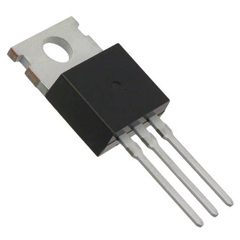
The IRF740 comes in a standard TO-220 package, which offers excellent thermal dissipation properties and easy mounting options. The pinout of the IRF740 is as follows:
| Pin | Name | Description |
|---|---|---|
| 1 | Gate | Controls the switching of the MOSFET |
| 2 | Drain | Main current-carrying terminal |
| 3 | Source | Ground reference and current return path |
It’s important to note that the metal tab of the TO-220 package is electrically connected to the drain terminal. Proper insulation and heat sinking considerations should be made when mounting the IRF740 to avoid short circuits and ensure efficient heat dissipation.

Operating Principles
To effectively use the IRF740 in your projects, it’s essential to understand its operating principles. As an N-channel enhancement-mode MOSFET, the IRF740 is normally off when no voltage is applied to the gate terminal. When a positive voltage exceeding the threshold voltage (VGS(th)) is applied to the gate, an electric field is created, forming a conductive channel between the drain and source terminals. This allows current to flow from the drain to the source, effectively turning the MOSFET on.
The amount of current flowing through the IRF740 is proportional to the gate voltage applied. As the gate voltage increases, the conductive channel becomes more pronounced, allowing more current to flow. This relationship between the gate voltage and drain current is known as the transfer characteristic curve.
It’s crucial to keep the gate-source voltage within the specified limits to prevent damage to the MOSFET. Applying a voltage beyond the maximum rating can lead to gate oxide breakdown and permanent damage to the device.
When the gate voltage is removed or falls below the threshold voltage, the conductive channel dissipates, and the IRF740 turns off, blocking current flow between the drain and source terminals.

Applications
The IRF740’s impressive power handling capabilities and fast switching speeds make it suitable for a wide range of applications. Some common applications include:
-
Motor Drives: The IRF740 can be used in motor control circuits to efficiently drive and regulate the speed of DC motors, such as those found in robotics, automotive systems, and industrial machinery.
-
Power Supplies: With its high voltage and current ratings, the IRF740 is an excellent choice for designing switch-mode power supplies (SMPS). It can be used in various topologies like buck converters, boost converters, and inverters to efficiently regulate and convert power.
-
Audio Amplifiers: The IRF740’s fast switching characteristics and low on-resistance make it suitable for use in class-D audio amplifiers. It can efficiently switch high currents to drive speakers while minimizing power losses and heat generation.
-
Battery Chargers: The IRF740 can be employed in battery charging circuits to control the charging current and voltage. Its high power handling capability allows for fast charging of high-capacity batteries.
-
Lighting Control: In LED lighting applications, the IRF740 can be used to control the brightness and dimming of LED arrays. Its fast switching capabilities enable precise control over the LED current, resulting in smooth dimming and color mixing.
-
Induction Heating: The IRF740 can be utilized in induction heating systems to generate high-frequency magnetic fields. Its high power handling capability and fast switching speeds make it suitable for driving induction coils efficiently.
These are just a few examples of the many applications where the IRF740 can be employed. Its versatility and robust performance make it a popular choice for a wide range of power electronics projects.

Driving the IRF740
To properly drive the IRF740 and ensure optimal performance, several factors need to be considered. Let’s explore some key aspects of driving the IRF740:
Gate Driver Circuit
The IRF740 requires a gate driver circuit to provide the necessary voltage and current to turn the MOSFET on and off efficiently. The gate driver should be able to supply a voltage higher than the threshold voltage (VGS(th)) to fully turn on the MOSFET and a voltage below the threshold to turn it off.
A common gate driver circuit for the IRF740 includes a microcontroller or a dedicated gate driver IC, such as the IR2110 or TC4420. These driver ICs provide the necessary voltage level shifting and current amplification to drive the MOSFET effectively.
When designing the gate driver circuit, it’s important to consider the gate charge and the required switching speed. The gate driver should be able to provide sufficient current to charge and discharge the gate capacitance quickly, ensuring fast switching transitions and minimizing power losses.
Gate Resistor
Adding a gate resistor between the gate driver output and the IRF740’s gate terminal is often recommended. The gate resistor serves several purposes:
- It limits the peak gate current during switching transitions, protecting the gate driver and the MOSFET from excessive current spikes.
- It slows down the switching speed slightly, reducing the potential for voltage overshoots and ringing that can occur due to parasitic inductances.
- It helps to dampen oscillations and improves stability in the gate drive circuit.
The value of the gate resistor depends on the specific application and the desired switching speed. Typical values range from a few ohms to a few hundred ohms. Experimentation and optimization may be necessary to find the optimal gate resistor value for your specific circuit.
Snubber Circuit
In some applications, especially those involving inductive loads or high switching frequencies, a snubber circuit may be necessary to protect the IRF740 from voltage spikes and reduce ringing. A snubber circuit consists of a resistor and a capacitor connected across the drain and source terminals of the MOSFET.
The snubber circuit absorbs the energy stored in the parasitic inductances during switching transitions, limiting the voltage spikes and reducing the stress on the MOSFET. It also helps to dampen oscillations and improve the overall stability of the circuit.
The values of the snubber resistor and capacitor depend on the specific application, the switching frequency, and the characteristics of the load. Proper design and optimization of the snubber circuit are crucial to ensure effective protection and reliable operation of the IRF740.
Thermal Considerations
Proper thermal management is essential when using the IRF740 to ensure reliable operation and prevent damage due to excessive heat. The IRF740 has a maximum junction temperature (TJ) of 175°C, beyond which its performance and reliability can be compromised.
To dissipate heat effectively, the IRF740 should be mounted on a suitable heatsink. The heatsink provides a thermal path for the heat generated by the MOSFET to be transferred to the ambient environment. The size and type of heatsink required depend on factors such as the power dissipation, ambient temperature, and airflow conditions.
When selecting a heatsink, consider its thermal resistance, which quantifies its ability to dissipate heat. A lower thermal resistance indicates better heat dissipation capability. The thermal resistance of the heatsink, along with the thermal resistance of the MOSFET and the interface material (e.g., thermal paste), determines the overall thermal performance of the system.
Proper mounting of the IRF740 on the heatsink is crucial for efficient heat transfer. The MOSFET should be securely attached to the heatsink using mounting hardware, such as screws or clips. A thermal interface material, like thermal paste or a thermal pad, should be applied between the MOSFET and the heatsink to fill any air gaps and enhance thermal conductivity.
In applications where the IRF740 is subjected to high power dissipation or operates in high-temperature environments, additional cooling techniques may be necessary. These can include forced air cooling using fans, liquid cooling systems, or heat pipes to improve heat dissipation and maintain the MOSFET within its safe operating temperature range.
Protection Considerations
To ensure the longevity and reliable operation of the IRF740, it’s important to implement appropriate protection measures in your circuit design. Some key protection considerations include:
-
Overcurrent Protection: Implementing overcurrent protection is essential to safeguard the IRF740 from excessive current that can cause damage. Techniques such as current sensing, fuses, or overcurrent detection circuits can be used to monitor the current and trigger a shutdown or limiting action when a predefined threshold is exceeded.
-
Overvoltage Protection: The IRF740 has a maximum drain-source voltage rating of 400V. Exceeding this voltage can lead to breakdown and permanent damage. Overvoltage protection mechanisms, such as transient voltage suppressors (TVS), Zener diodes, or voltage Clamping Circuits, can be employed to limit the voltage across the MOSFET and prevent overvoltage conditions.
-
Electrostatic Discharge (ESD) Protection: The IRF740, like most MOSFETs, is sensitive to electrostatic discharge. ESD events can cause damage to the gate oxide and degrade the performance of the MOSFET. Implementing ESD protection measures, such as using ESD-safe handling procedures, grounding equipment, and incorporating ESD protection devices (e.g., ESD diodes or varistors) in the circuit, can help mitigate the risk of ESD damage.
-
Reverse Polarity Protection: In applications where the IRF740 is used in a power supply or battery-powered circuit, protecting against reverse polarity connections is crucial. Reverse polarity can cause excessive current flow and damage the MOSFET. Techniques such as using a series diode, a MOSFET-based ideal diode circuit, or a polarity protection IC can be employed to prevent reverse polarity damage.
-
Gate-Source Voltage Limiting: Ensuring that the gate-source voltage remains within the specified limits is important to prevent gate oxide breakdown. Using a voltage clamping circuit, such as a Zener diode or a voltage divider, can help limit the gate-source voltage to a safe level.
By incorporating appropriate protection measures, you can enhance the robustness and reliability of your IRF740-based circuits, preventing damage and ensuring long-term performance.
FAQs
Q1: What is the maximum drain-source voltage of the IRF740?
A1: The maximum drain-source voltage (VDS) of the IRF740 is 400V.
Q2: What is the continuous drain current rating of the IRF740?
A2: The IRF740 has a continuous drain current (ID) rating of 10A.
Q3: How much power can the IRF740 dissipate?
A3: The IRF740 has a power dissipation (PD) rating of 125W.
Q4: What is the purpose of a gate resistor when driving the IRF740?
A4: A gate resistor is used to limit the peak gate current, slow down the switching speed slightly, and dampen oscillations, improving stability and protecting the gate driver and MOSFET.
Q5: Why is thermal management important when using the IRF740?
A5: Proper thermal management is crucial to ensure reliable operation and prevent damage to the IRF740 due to excessive heat. It involves using a suitable heatsink and proper mounting techniques to dissipate heat effectively and keep the MOSFET within its safe operating temperature range.
Conclusion
The IRF740 is a powerful and versatile N-channel MOSFET that finds applications in a wide range of electronics projects. Its high voltage and current ratings, fast switching speeds, and robust performance make it a popular choice among hobbyists and professionals alike.
By understanding the key features, operating principles, and application considerations of the IRF740, you can effectively utilize its capabilities in your projects. Proper circuit design, including gate driver configuration, snubber circuits, and protection measures, is essential to ensure optimal performance and reliability.
Thermal management is also a critical aspect when working with the IRF740. Selecting an appropriate heatsink, ensuring proper mounting, and implementing additional cooling techniques when necessary are vital for maintaining the MOSFET within its safe operating limits.
Armed with the knowledge provided in this comprehensive guide, you are now well-equipped to explore the vast possibilities offered by the IRF740. Whether you are designing motor drives, power supplies, audio amplifiers, or any other power electronics project, the IRF740 is a reliable and powerful component that can help bring your ideas to life.
So go ahead, unleash the potential of the IRF740 in your next electronics endeavor, and experience the power and versatility it brings to your designs!
No responses yet