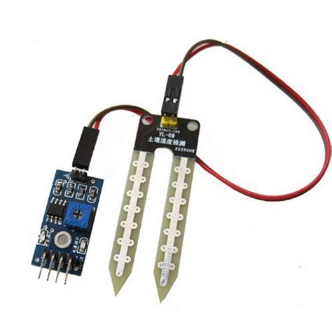
What is a Water Sensor?
A water sensor is a device that detects the presence or absence of water and provides an output signal based on the water level. There are various types of water sensors, including:
- Conductivity-based sensors
- Capacitive sensors
- Ultrasonic Sensors
- Float switches
Each type of sensor has its own advantages and disadvantages, and the choice of sensor depends on the specific application requirements.
How Does a Water Sensor Circuit Work?
A basic water sensor circuit consists of the following components:
- Water sensor probe
- Resistors
- Transistor
- LED
- Power source
The water sensor probe is typically made of two conductive materials, such as copper or aluminum, separated by an insulating material. When the probe comes in contact with water, it creates a conductive path between the two materials, allowing current to flow through the circuit.
The resistors in the circuit help to limit the current flow and protect the other components from damage. The transistor acts as a switch, turning on or off based on the presence or absence of water. The LED provides a visual indication of the water level, while the power source, such as a battery, supplies the necessary voltage to the circuit.

Building a Simple Water Sensor Circuit
To build a simple water sensor circuit, you will need the following components:
| Component | Quantity |
|---|---|
| Water sensor probe | 1 |
| 10kΩ resistor | 1 |
| 2.2kΩ resistor | 1 |
| BC547 transistor | 1 |
| LED | 1 |
| 9V battery | 1 |
Follow these steps to assemble the circuit:
- Connect one end of the water sensor probe to the positive terminal of the battery.
- Connect the other end of the probe to the collector of the transistor and one end of the 10kΩ resistor.
- Connect the other end of the 10kΩ resistor to the base of the transistor.
- Connect the emitter of the transistor to one end of the 2.2kΩ resistor.
- Connect the other end of the 2.2kΩ resistor to the negative terminal of the battery.
- Connect the anode (longer leg) of the LED to the collector of the transistor.
- Connect the cathode (shorter leg) of the LED to the negative terminal of the battery.
When the water sensor probe comes in contact with water, the transistor will turn on, allowing current to flow through the LED, causing it to light up. When the probe is not in contact with water, the transistor will turn off, and the LED will remain off.

Calibrating the Water Sensor Circuit
To ensure accurate readings from your water sensor circuit, it is essential to calibrate it properly. Calibration involves adjusting the circuit’s sensitivity to detect the desired water level. This can be done by adjusting the values of the resistors in the circuit.
For example, if you want the LED to light up when the water level reaches a specific height, you can adjust the value of the 10kΩ resistor. Increasing the resistance will make the circuit less sensitive, requiring more water to activate the LED, while decreasing the resistance will make the circuit more sensitive, requiring less water to activate the LED.

Applications of Water Sensor Circuits
Water sensor circuits have a wide range of applications, including:
Agriculture
In agriculture, water sensor circuits can be used to monitor soil moisture levels and control irrigation systems. By placing the sensor probes at different depths in the soil, farmers can determine when and how much to water their crops, ensuring optimal growth and reducing water waste.
Flood Detection
Water sensor circuits can be used to detect and alert authorities about potential flood situations. By placing the sensors at critical points along rivers, canals, or low-lying areas, early warning systems can be implemented to prevent damage to life and property.
Water Level Monitoring in Tanks
Water sensor circuits can be used to monitor the water level in storage tanks, ensuring a constant supply of water for various purposes. When the water level drops below a certain point, the sensor can trigger a pump to refill the tank, maintaining a consistent water level.
Leak Detection
Water sensor circuits can be used to detect leaks in pipes, tanks, or other water-containing structures. By placing the sensors at strategic locations, any leaks can be quickly identified and repaired, preventing water loss and potential damage.
Frequently Asked Questions (FAQ)
- What is the difference between a conductivity-based water sensor and a capacitive water sensor?
-
A conductivity-based water sensor detects the presence of water by measuring the electrical conductivity between two probes, while a capacitive water sensor measures the change in capacitance caused by the presence of water.
-
Can a water sensor circuit be used with saltwater?
-
Yes, a water sensor circuit can be used with saltwater, as saltwater is an excellent conductor of electricity. However, the sensor probes may corrode more quickly due to the salt content, so it is essential to use corrosion-resistant materials or protective coatings.
-
How can I make my water sensor circuit more accurate?
-
To improve the accuracy of your water sensor circuit, you can use higher-quality components, calibrate the circuit properly, and ensure that the sensor probes are clean and free from debris. Additionally, using a more advanced sensor, such as an ultrasonic sensor, can provide more precise readings.
-
Can I use a water sensor circuit to measure the depth of water?
-
While a simple water sensor circuit can detect the presence or absence of water, it cannot directly measure the depth of water. To measure water depth, you would need to use a more advanced sensor, such as an ultrasonic sensor or a pressure sensor.
-
How can I integrate a water sensor circuit with an Arduino or other microcontroller?
- To integrate a water sensor circuit with an Arduino or other microcontroller, you can connect the output of the sensor circuit to one of the microcontroller’s digital input pins. The microcontroller can then read the state of the sensor and perform actions based on the water level, such as triggering an alarm or controlling a pump.
In conclusion, water sensor circuits are essential tools for monitoring and managing water levels in various applications. By understanding the basics of how these circuits work and how to build and calibrate them, you can create effective solutions for water level monitoring in agriculture, flood detection, tank management, and leak detection. As you explore more advanced sensors and integrate them with microcontrollers, the possibilities for water level monitoring and control are virtually endless.
No responses yet