Introduction to the UC3844
The UC3844 is a fixed frequency current mode PWM controller commonly used in switched mode power supplies (SMPS). It is designed to control offline flyback and forward converters at frequencies up to 500kHz. The UC3844 provides excellent performance with features like undervoltage lockout, maximum duty cycle limit, built-in soft-start, and current sensing.
Some key features of the UC3844 include:
- Wide operating voltage range (10V to 30V)
- Low startup current (<1mA)
- Built-in oscillator with frequency up to 500kHz
- Pulse-by-pulse current limiting
- Undervoltage lockout and soft-start
- Totem pole output capable of sinking/sourcing peak 1A currents
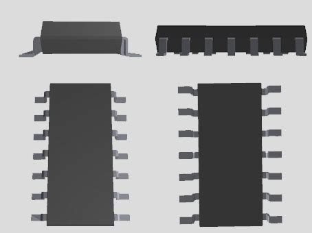
The UC3844 is available in 8-pin PDIP, SOIC-8 and other packages. It is a popular choice for designing efficient and reliable power converters in the 10W to 200W output power range.
UC3844 Pinout and Pin Functions
The UC3844 comes in an 8-pin package with the following pinout:
| Pin # | Pin Name | Description |
|---|---|---|
| 1 | COMP | Error amplifier output/PWM comparator input |
| 2 | FB | Feedback voltage input |
| 3 | CS | Current sense input |
| 4 | RC | Oscillator timing resistor input |
| 5 | GND | Ground |
| 6 | OUT | Output to MOSFET gate driver |
| 7 | VCC | Positive supply voltage |
| 8 | REF | 5V reference voltage output |
Here is a brief description of each pin’s function:
COMP (Pin 1)
This is the output of the error amplifier and one of the inputs to the PWM comparator. An RC network from this pin to ground compensates the regulator feedback loop.
FB (Pin 2)
This is the inverting input of the error amplifier which senses the feedback voltage to regulate the output voltage. Usually connected through a resistor divider from the output.
CS (Pin 3)
Current sense input. This is connected to the current sensing resistor. A voltage of 1V on this pin will terminate the output pulse.
RC (Pin 4)
A resistor from this pin to ground sets the oscillator frequency according to:
f = 1.72 / (R × C)
GND (Pin 5)
Circuit ground.
OUT (Pin 6)
Totem pole output that drives the gate of the external MOSFET. Capable of sinking and sourcing peak currents up to 1A.
VCC (Pin 7)
Positive supply input. Needs at least 10V to operate. Usually powered by an auxiliary winding on the power transformer.
REF (Pin 8)
Provides a 5V reference voltage. Can be used to bias the error amplifier and set undervoltage lockout thresholds with an external resistor divider.

UC3844 Block Diagram
The internal block diagram of the UC3844 is shown below:
The main functional blocks are:
-
Undervoltage Lockout (UVLO): Monitors the VCC pin and keeps the IC shut down until VCC rises above the startup threshold voltage (typically 16V). Has about 6V of hysteresis.
-
Reference Regulator: Provides a precise 5V reference voltage on the REF pin which is used internally and can also power external circuitry.
-
Oscillator: Generates the fixed frequency clock based on the RC timing components on pin 4. The maximum duty cycle is limited to less than 50% internally.
-
Error Amplifier: Amplifies the difference between the 2.5V reference and external feedback signal on the FB pin. The COMP pin (pin 1) provides access to the output for loop frequency compensation.
-
Current Sense Comparator: Terminates the output pulse when voltage on the CS pin exceeds 1V, providing cycle-by-cycle current limiting.
-
PWM Comparator: Compares the error amplifier output to the current sense signal to generate the PWM duty cycle. Output goes high when error amp > current sense.
-
PWM Latch: Turned on by the oscillator clock and turned off by the PWM comparator or the 50% duty cycle limit.
-
Output Stage: Totem pole output that drives the external MOSFET gate. Has a high current sink/source capability for fast switching.
-
Soft-Start: Gradually increases the error amp reference on startup to provide a controlled output voltage rise time.
With these functional blocks, the UC3844 implements voltage mode control and cycle-by-cycle current limiting in an SMPS. The error amp senses the output voltage and adjusts the duty cycle while the current sense comparator provides overcurrent protection.

Flyback Converter Using UC3844
One of the most common applications of the UC3844 is in an isolated flyback converter. The schematic below shows a typical implementation:
The AC line voltage is rectified by D1-D4 and filtered by capacitor C1 to generate a high voltage DC bus. When the MOSFET Q1 is on, current ramps up in the primary winding of transformer T1, storing energy in the magnetic field. When Q1 turns off, the energy transfers to the secondary winding and forward biases diode D5. The current then flows into the output capacitor C3 and the load.
The output voltage is regulated by the UC3844 controller. Resistors R1 and R2 form a voltage divider that senses a fraction of the output voltage and feeds it back to the FB pin (pin 2). The error amp compares this feedback voltage to an internal 2.5V reference and generates an error signal on the COMP pin. This error signal is then compared to the current sense signal from resistor R5 by the PWM comparator. The comparator output drives the PWM latch which generates the gate drive waveform for Q1.
When the output voltage is too low, the error amp output increases, causing the duty cycle to increase and raise the output voltage. Conversely, when the output is too high, the duty cycle decreases until the desired voltage is reached. Resistor R4 and capacitor C4 provide high frequency compensation for the feedback loop.
The oscillator frequency is set by resistor R3 and capacitor C2 according to:
f = 1.72 / (R3 × C2)
Capacitor C5 connected to the COMP pin (pin 1) provides additional low frequency compensation to stabilize the loop. The soft-start feature gradually increases the duty cycle on startup, preventing high inrush currents. Finally, resistor R5 senses the current through Q1 and terminates the PWM pulse if the voltage exceeds 1V, providing overcurrent protection.
This typical application demonstrates how the UC3844 can be used to efficiently regulate an isolated flyback converter. Only a handful of external components are required. The UC3844 simplifies the design by integrating many important control and protection features.

UC3844 versus UC3842/UC3843
The UC3844 is a close relative of the popular UC3842/UC3843 PWM controllers. The key differences are:
| Feature | UC3842/3 | UC3844 |
|---|---|---|
| Max Frequency | 500kHz | 500kHz |
| UVLO Thresholds | 8.4V/7.6V | 16V/10V |
| Max Duty Cycle | 100% | 50% |
| Soft-Start | No | Yes |
| Packages | 8-pin DIP, SOIC, PDIP | 8-pin DIP, SOIC, PDIP |
The main differences are the UVLO thresholds, maximum duty cycle and the addition of soft-start in the UC3844. The UC3844’s higher UVLO thresholds are tailored for off-line applications, while the UC3842/3 are better suited for lower voltage DC-DC converters.
The UC3844’s 50% max duty cycle is ideal for discontinuous mode flyback converters as it prevents saturation of the transformer. The UC3842/3 allow up to 100% duty cycle which is useful in continuous mode operation.
Overall, the UC3844 offers a few enhancements over the UC3842/3 that make it better optimized for higher voltage off-line SMPS applications. But they are similar enough that the UC3844 can be used as a drop-in replacement in many designs.
Conclusion
In summary, the UC3844 is a versatile fixed frequency current mode PWM controller IC that enables simple and efficient designs for isolated off-line SMPS. With a 500kHz max oscillator frequency, built-in protection features, and a robust totem pole output, it is well suited for flyback and forward converters in the 10W to 200W power range.
The UC3844 offers many integrated features that simplify the design of an SMPS:
- Wide supply range with undervoltage lockout
- Fixed frequency oscillator up to 500kHz
- Built-in soft-start to limit inrush current
- Cycle-by-cycle current limiting for overload protection
- High current totem pole MOSFET driver
- Precision 5V reference voltage
A complete off-line flyback converter can be built with the UC3844 and a handful of external components. Its close compatibility with the UC3842/3 controllers allows it to be easily retrofitted into existing designs with some key performance enhancements.
For designers looking to quickly implement an efficient and cost-effective isolated power supply solution, the UC3844 is an excellent choice. Its robust feature set and ease-of-use make it a go-to controller for many low to medium power SMPS applications.
FAQ
What is the maximum switching frequency of the UC3844?
The UC3844 has a maximum oscillator frequency of 500kHz, set by an external resistor and capacitor on the RC pin (pin 4).
What type of converter topologies can the UC3844 be used in?
The UC3844 is optimized for isolated flyback and forward converters in the 10W to 200W output power range. It can also be used in non-isolated applications.
How does the UC3844 provide output overload protection?
The UC3844 has a cycle-by-cycle current limit feature that terminates the output pulse if the current sense voltage on the CS pin exceeds 1V. This protects the converter from excessive current during output short circuit or overload conditions.
What is the maximum duty cycle of the UC3844?
The UC3844 limits the maximum duty cycle to less than 50%. This is to prevent transformer saturation in discontinuous mode flyback converters. For applications requiring higher duty cycles, the UC3842/3 controllers can be used which allow up to 100% duty cycle.
What is the purpose of the soft-start feature?
The soft-start gradually increases the duty cycle on startup, reducing high inrush currents that can occur when charging the output capacitors. This helps to minimize stress on the power components. The UC3844 has a built-in 1ms soft-start whereas the UC3842/3 do not include this feature.
No responses yet