Introduction to Rectifier Circuits
A rectifier circuit is an essential component in electronic systems that converts alternating current (AC) to direct current (DC). This conversion is crucial for powering various electronic devices, such as smartphones, computers, and televisions, which require a steady supply of DC power. In this comprehensive article, we will delve into the general basics of rectifier circuits, their working principles, and the requirements for designing an efficient rectifier circuit.
What is a Rectifier Circuit?
A rectifier circuit is an electronic circuit that converts AC voltage, which periodically reverses direction, into DC voltage, which flows in only one direction. The process of converting AC to DC is known as rectification. Rectifier circuits are widely used in power supplies, Battery Chargers, and various other electronic applications where a steady DC voltage is required.
Types of Rectifier Circuits
There are several types of rectifier circuits, each with its own characteristics and applications. The most common types of rectifier circuits are:
- Half-wave rectifier
- Full-wave rectifier
- Center-tapped transformer full-wave rectifier
- Bridge rectifier
Half-Wave Rectifier
A half-wave rectifier is the simplest type of rectifier circuit. It consists of a single diode connected in series with the load. During the positive half-cycle of the AC input, the diode conducts, allowing current to flow through the load. During the negative half-cycle, the diode blocks the current, resulting in no output. The output of a half-wave rectifier is a pulsating DC voltage with a frequency equal to the input AC frequency.
Full-Wave Rectifier
A full-wave rectifier is an improvement over the half-wave rectifier, as it utilizes both half-cycles of the AC input to produce a DC output. There are two main types of full-wave rectifiers:
-
Center-tapped transformer full-wave rectifier: This type of rectifier uses a center-tapped transformer and two diodes. The center tap of the transformer secondary winding is connected to the ground or common point, and each end of the secondary winding is connected to a diode. The diodes conduct alternately during each half-cycle of the AC input, producing a full-wave rectified output.
-
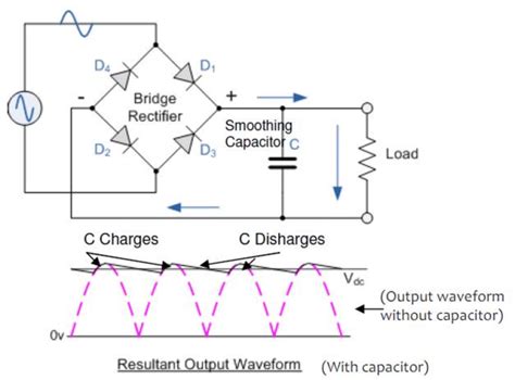
Bridge rectifier: A bridge rectifier consists of four diodes arranged in a bridge configuration. During the positive half-cycle of the AC input, two diodes conduct, allowing current to flow through the load in one direction. During the negative half-cycle, the other two diodes conduct, maintaining the same direction of current flow through the load. The output of a bridge rectifier is a full-wave rectified DC voltage.
Comparison of Rectifier Circuits
| Rectifier Type | Efficiency | Ripple Frequency | Transformer Utilization |
|---|---|---|---|
| Half-Wave | Low | Input frequency | Poor |
| Full-Wave (Center-Tapped) | High | 2 × Input frequency | Good |
| Full-Wave (Bridge) | High | 2 × Input frequency | Excellent |

Working Principle of Rectifier Circuits
The working principle of rectifier circuits is based on the unidirectional current flow property of diodes. A diode is a semiconductor device that allows current to flow in only one direction, from its anode to its cathode. When the anode is positively biased with respect to the cathode, the diode conducts, allowing current to flow. When the anode is negatively biased, the diode blocks the current flow.
Half-Wave Rectifier Working
In a half-wave rectifier, the diode is connected in series with the load. During the positive half-cycle of the AC input, the diode is forward-biased, allowing current to flow through the load. During the negative half-cycle, the diode is reverse-biased, blocking the current flow. As a result, the output voltage across the load is a pulsating DC voltage with a frequency equal to the input AC frequency.
Full-Wave Rectifier Working
In a full-wave rectifier, two diodes are used to rectify both half-cycles of the AC input. In the center-tapped transformer configuration, each diode conducts alternately during each half-cycle, producing a full-wave rectified output. In the bridge rectifier configuration, two diodes conduct during each half-cycle, maintaining the same direction of current flow through the load. The output of a full-wave rectifier is a pulsating DC voltage with a frequency twice that of the input AC frequency.

Rectifier Circuit Requirements
To design an efficient rectifier circuit, several requirements must be considered:
-
Diode selection: The diodes used in the rectifier circuit should have a sufficient peak inverse voltage (PIV) rating to withstand the maximum reverse voltage across them. The forward current rating of the diodes should also be higher than the maximum load current.
-
Transformer selection: The transformer used in the rectifier circuit should have the appropriate voltage rating and current rating to match the load requirements. In the case of a center-tapped transformer, the secondary winding should have a center tap connection.
-
Filter design: To reduce the ripple in the rectified output voltage, a filter circuit is often used. The filter can be a capacitor, an inductor, or a combination of both. The filter components should be selected based on the required ripple reduction and the load current.
-
Load considerations: The rectifier circuit should be designed to handle the maximum load current and the expected load variations. The voltage regulation of the rectifier circuit should be adequate to maintain a stable output voltage under varying load conditions.

FAQs
-
What is the difference between a half-wave rectifier and a full-wave rectifier?
A half-wave rectifier uses only one half-cycle of the AC input to produce a pulsating DC output, while a full-wave rectifier utilizes both half-cycles to produce a full-wave rectified output with twice the frequency of the input AC. -
Can a rectifier circuit be used to charge batteries?
Yes, rectifier circuits are commonly used in battery chargers to convert AC power from the mains into DC power suitable for charging batteries. -
What is the purpose of a filter in a rectifier circuit?
The purpose of a filter in a rectifier circuit is to reduce the ripple in the rectified output voltage, resulting in a smoother DC voltage. The filter can be a capacitor, an inductor, or a combination of both. -
How do I select the appropriate diodes for a rectifier circuit?
When selecting diodes for a rectifier circuit, consider the peak inverse voltage (PIV) rating, which should be higher than the maximum reverse voltage across the diodes, and the forward current rating, which should be higher than the maximum load current. -
Can a rectifier circuit be used for high-power applications?
Yes, rectifier circuits can be used for high-power applications, such as industrial power supplies and motor drives. However, for high-power applications, the rectifier Circuit Components, such as diodes and transformers, must be appropriately rated to handle the required current and voltage levels.
Conclusion
Rectifier circuits play a vital role in converting AC voltage to DC voltage, which is essential for powering various electronic devices. Understanding the general basics, working principles, and requirements of rectifier circuits is crucial for designing efficient and reliable power supply systems. By selecting the appropriate rectifier circuit topology, diodes, transformers, and filter components, designers can create rectifier circuits that meet the specific needs of their applications.
No responses yet