Understanding PCB Hole Sizes
Common Hole Sizes in PCB Manufacturing
PCB hole sizes can vary depending on the specific requirements of the components and the overall design of the circuit board. Here are some common hole sizes found in PCB manufacturing:
| Hole Size (mm) | Typical Use |
|---|---|
| 0.2 – 0.4 | Small vias, fine-pitch components |
| 0.5 – 0.8 | Standard through-hole components |
| 0.9 – 1.2 | Larger through-hole components, connectors |
| 1.3 – 2.0 | Power components, mounting holes |
| 2.1 – 3.0 | Specialized components, mechanical fasteners |
It’s essential to choose the appropriate hole size based on the component specifications and the PCB design guidelines to ensure proper fit and functionality.
Factors Affecting PCB Hole Size Selection
When selecting PCB hole sizes, several factors should be taken into consideration:
- Component requirements: The hole size must match the lead diameter or mounting requirements of the components being used.
- PCB Thickness: Thicker PCBs may require larger hole sizes to maintain the aspect ratio and ensure reliable plating.
- Manufacturing constraints: The capabilities of the PCB manufacturer, such as the minimum drill bit size and the drilling accuracy, should be considered.
- Electrical performance: Hole size can impact the electrical characteristics of the PCB, such as impedance and signal integrity.
- Mechanical strength: Larger hole sizes may be necessary for components subjected to mechanical stress or vibration.
By carefully evaluating these factors, you can determine the optimal hole sizes for your specific PCB design.
PCB Drilling Techniques
Mechanical Drilling
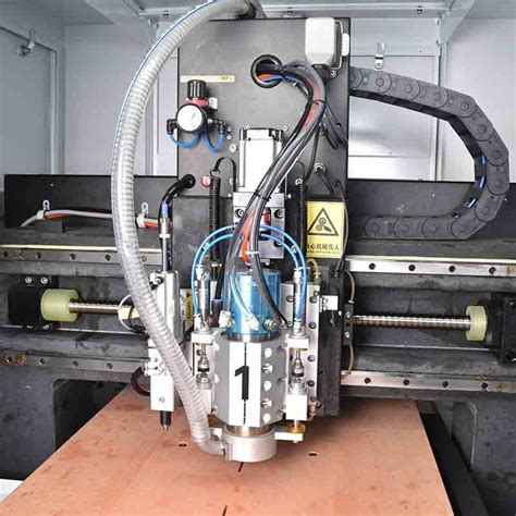
Mechanical drilling is the most common method for creating holes in PCBs. It involves using high-speed drill bits to physically remove material from the PCB substrate. Here are some key points about mechanical drilling:
- Drill bits are typically made of carbide or diamond-coated materials for durability and precision.
- Drilling speeds and feed rates are adjusted based on the hole size, PCB material, and drill bit characteristics.
- Proper drilling parameters, such as spindle speed and depth control, are crucial for achieving clean and accurate holes.
- Mechanical drilling is suitable for a wide range of hole sizes and can handle multiple layers of PCBs.
Laser Drilling
Laser drilling is an advanced technique that uses focused laser beams to create holes in PCBs. It offers several advantages over mechanical drilling:
- Laser drilling can create smaller and more precise holes, down to micron-level sizes.
- It is a non-contact process, eliminating the need for physical drill bits and reducing wear and tear on equipment.
- Laser drilling is faster than mechanical drilling, especially for high-density PCBs with numerous small holes.
- It can handle delicate materials and create holes at specific angles or in hard-to-reach areas.
However, laser drilling equipment is more expensive than mechanical drilling machines, and the process may not be suitable for all PCB materials or thicknesses.
Punching
Punching is another method for creating holes in PCBs, particularly for larger hole sizes or irregular shapes. It involves using a punch and die set to cut through the PCB material. Punching offers the following advantages:
- It is a fast and efficient process for creating large quantities of identical holes.
- Punching can handle thicker PCBs and create holes with clean edges.
- It is suitable for creating non-circular holes or slots in PCBs.
However, punching requires specialized tooling and may not be as versatile as mechanical or laser drilling for creating a wide range of hole sizes.

Best Practices for PCB Drilling
To achieve optimal results in PCB drilling, consider the following best practices:
- Drill bit selection: Choose the appropriate drill bit material, diameter, and geometry based on the hole size, PCB material, and drilling requirements.
- Drilling parameters: Set the drilling speed, feed rate, and depth control according to the manufacturer’s recommendations and the specific PCB characteristics.
- Hole placement: Ensure accurate hole placement by using precise alignment techniques and considering the tolerances specified in the PCB design.
- Debris removal: Implement effective debris removal methods, such as vacuum systems or compressed air, to prevent contamination and ensure clean holes.
- Inspection and quality control: Regularly inspect the drilled holes for accuracy, cleanliness, and consistency using microscopes or automated inspection systems.
- Maintenance and calibration: Perform regular maintenance and calibration of the drilling equipment to maintain accuracy and prolong the life of the machinery.
By following these best practices, you can optimize the PCB drilling process and achieve high-quality holes that meet your design requirements.

Frequently Asked Questions (FAQ)
-
What is the minimum hole size that can be drilled in a PCB?
The minimum hole size that can be drilled in a PCB depends on the capabilities of the drilling equipment and the PCB manufacturer. Typically, mechanical drilling can achieve hole sizes down to 0.2 mm, while laser drilling can create even smaller holes, down to micron-level sizes. -
How do I choose the right drill bit for my PCB?
When choosing a drill bit for your PCB, consider factors such as the hole size, PCB material, and drilling requirements. Consult with your PCB manufacturer or refer to drill bit manufacturers’ guidelines to select the appropriate drill bit material, diameter, and geometry for your specific application. -
Can I use the same drill bit for different hole sizes?
No, it is not recommended to use the same drill bit for different hole sizes. Each hole size requires a specific drill bit diameter to ensure accurate and clean holes. Using the wrong drill bit size can lead to inaccurate holes, damaged drill bits, or even damage to the PCB. -
How often should I replace the drill bits?
The frequency of drill bit replacement depends on various factors, such as the material being drilled, the drilling parameters, and the overall usage. It’s essential to regularly inspect the drill bits for wear and tear and replace them when necessary to maintain drilling accuracy and prevent damage to the PCB. -
What are the advantages of using laser drilling for PCBs?
Laser drilling offers several advantages for PCBs, including the ability to create smaller and more precise holes, faster drilling speeds for high-density PCBs, non-contact processing that reduces wear and tear on equipment, and the capability to handle delicate materials or create holes at specific angles. However, laser drilling equipment is more expensive compared to mechanical drilling machines.

Conclusion
PCB hole size and drilling techniques play a critical role in the manufacturing process of printed circuit boards. Understanding the common hole sizes, factors affecting hole size selection, and the different drilling methods available can help you make informed decisions when designing and manufacturing PCBs. By following best practices for PCB drilling, such as proper drill bit selection, optimized drilling parameters, and regular maintenance, you can achieve high-quality holes that meet your design requirements and ensure the reliability of your final product. As technology advances, new drilling techniques and equipment may emerge, offering even greater precision and efficiency in PCB manufacturing.
No responses yet