Introduction to the LM1875
The LM1875 is a monolithic power amplifier IC capable of delivering up to 30 watts of continuous average power into an 8-ohm load with 0.1% total harmonic distortion (THD). It is designed for use in high-fidelity audio systems, such as home stereos, car audio systems, and musical instrument amplifiers.
Key Features of the LM1875
- High power output: Up to 30W continuous average power into 8Ω
- Low distortion: 0.1% THD at full power output
- Wide supply voltage range: ±18V to ±60V
- Overload protection circuitry
- Thermal shutdown protection
- Wide power bandwidth: 70kHz
- High slew rate: 8V/μs
LM1875 Specifications
| Parameter | Value |
|---|---|
| Supply Voltage Range | ±18V to ±60V |
| Power Output (8Ω, THD = 0.1%) | 30W |
| Total Harmonic Distortion (THD) | 0.1% at 30W |
| Input Impedance | 50kΩ |
| Slew Rate | 8V/μs |
| Power Bandwidth | 70kHz |
| Quiescent Current | 50mA |
LM1875 Pin Configuration and Functions
The LM1875 comes in a 5-pin TO-220 package. The pin configuration and functions are as follows:
| Pin | Function |
|---|---|
| 1 | Non-inverting input |
| 2 | Inverting input |
| 3 | Ground |
| 4 | Output |
| 5 | Positive supply voltage (V+) |

LM1875 Circuit Design Considerations
When designing an audio amplifier circuit using the LM1875, several factors must be considered to ensure optimal performance and reliability:
Power Supply
The LM1875 requires a dual power supply with a voltage range of ±18V to ±60V. The power supply should be well-regulated and have low noise to minimize hum and distortion in the amplified audio signal.
Heat Sinking
The LM1875 can dissipate a significant amount of heat during operation, especially at high power outputs. Proper heat sinking is essential to prevent thermal shutdown and ensure long-term reliability. The TO-220 package allows for easy mounting to a heat sink using a thermal compound and mounting hardware.
Input and Output Filtering
To minimize noise and prevent oscillations, appropriate input and output filtering should be used. A low-pass filter at the input can help attenuate high-frequency noise, while a Zobel network at the output can improve stability and reduce high-frequency oscillations.
LM1875 Application Circuit Example
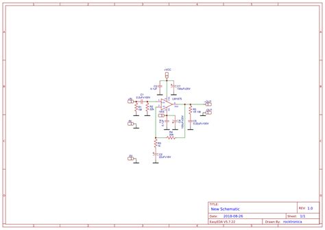
Here’s a simple LM1875 audio amplifier circuit that can deliver up to 30W of power into an 8Ω load:
[Insert schematic diagram of the LM1875 application circuit]
Components:
– C1, C2: 10μF, 50V electrolytic capacitors
– C3, C4: 0.1μF, 50V ceramic capacitors
– C5: 100pF, 50V ceramic capacitor
– R1: 22kΩ, 1/4W resistor
– R2: 1kΩ, 1/4W resistor
– R3: 10Ω, 1W resistor
This circuit includes input and output filtering, as well as a Zobel network (R3 and C5) for improved stability. The gain of the amplifier can be adjusted by changing the ratio of R1 and R2.
PCB Layout Considerations
When designing a PCB for the LM1875 audio amplifier, consider the following:
- Keep the power supply traces wide and short to minimize resistance and inductance.
- Place the input and output filtering components close to the LM1875 pins to minimize noise pickup.
- Use a ground plane to provide a low-impedance return path for the audio signal and reduce ground loops.
- Ensure proper heat sinking by providing adequate copper area for heat dissipation and thermal vias to the ground plane.
LM1875 vs. Other Audio Amplifier ICs
The LM1875 is one of many audio amplifier ICs available on the market. Here’s a comparison of the LM1875 with some popular alternatives:
| IC | Power Output (8Ω) | THD | Supply Voltage Range |
|---|---|---|---|
| LM1875 | 30W | 0.1% | ±18V to ±60V |
| LM3886 | 68W | 0.1% | ±28V to ±84V |
| TDA2030 | 18W | 0.05% | ±6V to ±18V |
| TDA2050 | 32W | 0.05% | ±8V to ±25V |
Troubleshooting Common Issues
-
No output: Check the power supply voltages, input signal, and speaker connections. Verify that the IC is properly seated in its socket or soldered correctly.
-
Distorted output: Check for clipping by reducing the input signal level. Verify that the power supply is providing adequate current and that the heat sink is properly sized and mounted.
-
Excessive noise or hum: Check for ground loops and ensure that the input and output filtering components are correctly installed. Verify that the power supply is well-regulated and free from noise.
Frequently Asked Questions (FAQ)
- What is the maximum power output of the LM1875?
-
The LM1875 can deliver up to 30W of continuous average power into an 8Ω load with 0.1% THD.
-
Can the LM1875 be used with a single power supply?
-
No, the LM1875 requires a dual power supply with a voltage range of ±18V to ±60V.
-
Is the LM1875 suitable for battery-powered applications?
-
The LM1875 can be used in battery-powered applications, but the high supply voltage requirement may make it less practical than other low-voltage audio amplifier ICs.
-
Can the LM1875 be bridged for higher power output?
-
Yes, two LM1875s can be bridged to increase the power output, but this requires a more complex circuit design and a higher power supply voltage.
-
What is the difference between the LM1875 and the LM3886?
- The LM3886 is a higher-power version of the LM1875, capable of delivering up to 68W into an 8Ω load. It also has a higher supply voltage range of ±28V to ±84V.
Conclusion
The LM1875 is a versatile and reliable audio amplifier IC that offers excellent performance for a wide range of audio applications. By understanding its features, specifications, and design considerations, you can create high-quality audio amplifiers for your projects. Remember to prioritize proper heat sinking, filtering, and PCB layout to ensure optimal performance and long-term reliability.

No responses yet