Introduction to Trimpots
A trimpot, short for trimming potentiometer, is a small, adjustable resistor that allows for precise tuning of electrical circuits. These versatile components are widely used in various electronic applications, from calibrating sensors to fine-tuning audio equipment. Understanding the Trimpot Pinout is essential for effectively utilizing these components in your projects.
What is a Trimpot?
A trimpot is a three-terminal variable resistor that consists of a resistive element and a wiper. The wiper is a movable contact that slides along the resistive element, allowing you to adjust the resistance between the two outer terminals. Trimpots come in various sizes, resistance ranges, and configurations to suit different applications.
Trimpot vs. Potentiometer
While trimpots and potentiometers share similarities in their basic functioning, there are some key differences between the two:
| Feature | Trimpot | Potentiometer |
|---|---|---|
| Size | Smaller, typically SMD or through-hole | Larger, often panel-mounted |
| Adjustment | Requires a small screwdriver | Can be adjusted by hand |
| Rotation | Limited rotation (usually 270°) | Continuous rotation (360°) |
| Application | Circuit calibration and fine-tuning | User-adjustable controls |
Trimpot Pinout and Configuration
To effectively use trimpots in your projects, it’s crucial to understand their pinout and how to configure them correctly.
Standard Trimpot Pinout
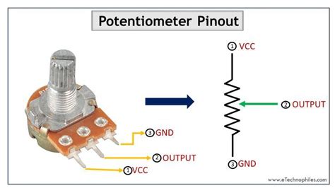
Most trimpots follow a standard pinout configuration, regardless of their package type (SMD or through-hole). The three pins are typically labeled as follows:
- Pin 1: One end of the resistive element
- Pin 2: Wiper (adjustable terminal)
- Pin 3: The other end of the resistive element
Here’s a visual representation of a standard trimpot pinout:
   +---------+
 1 |         | 3
   |    2    |
   +---------+
Configuring Trimpots
Trimpots can be configured in three primary ways, depending on your circuit requirements:
-
Variable Resistor: Connect one end of the resistive element (Pin 1 or 3) to ground or the positive supply, and use the wiper (Pin 2) as the variable resistance output. Leave the other end of the resistive element unconnected.
-
Voltage Divider: Connect one end of the resistive element (Pin 1 or 3) to the positive supply and the other end to ground. Use the wiper (Pin 2) as the variable voltage output.
-
Rheostat: Connect the wiper (Pin 2) to one end of the resistive element (Pin 1 or 3), and use these two pins as the variable resistance. Leave the other end of the resistive element unconnected.

Trimpot Characteristics and Specifications
When selecting a trimpot for your project, consider the following characteristics and specifications:
Resistance Range
Trimpots are available in various resistance ranges, typically from a few ohms to several megaohms. Choose a trimpot with a resistance range suitable for your application.
Power Rating
The power rating indicates the maximum amount of power the trimpot can dissipate without damage. Ensure that the expected power dissipation in your circuit does not exceed the trimpot’s power rating.
Linearity
Linearity refers to how closely the resistance change follows a straight line as the wiper is adjusted. High-linearity trimpots provide a more precise and predictable resistance change.
Temperature Coefficient
The temperature coefficient indicates how much the resistance value changes with temperature variations. Lower temperature coefficients ensure more stable performance across different operating temperatures.
Adjustment Type
Trimpots can have different adjustment types, such as top-adjust or side-adjust, which determine how you access the adjustment screw. Choose an adjustment type that suits your mounting and accessibility requirements.

Applications of Trimpots
Trimpots find use in a wide range of electronic applications, including:
-
Sensor Calibration: Trimpots are often used to calibrate sensors, such as temperature, pressure, or Light Sensors, by adjusting their output to match a known reference value.
-
Voltage Reference Adjustment: In power supplies and Voltage Regulators, trimpots can be used to fine-tune the output voltage to a precise value.
-
Offset and Gain Adjustment: Trimpots are used to adjust the offset and gain of amplifiers, ensuring optimal performance and accuracy.
-
Frequency Tuning: In oscillators and filters, trimpots allow for precise frequency adjustment and calibration.
-
Audio Equipment: Trimpots are used in audio equipment for volume control, tone control, and balancing audio channels.

Trimpot Mounting and Adjustment
Mounting Trimpots
Trimpots can be mounted on PCBs using various methods, depending on their package type:
-
SMD Trimpots: Surface-mount trimpots are soldered directly onto the PCB pads, providing a compact and space-saving solution.
-
Through-Hole Trimpots: Through-hole trimpots have pins that are inserted through holes in the PCB and soldered on the opposite side. This method provides a more robust mechanical connection.
Adjusting Trimpots
To adjust a trimpot, use a small flathead screwdriver that fits the adjustment screw. Gently turn the screw clockwise or counterclockwise to increase or decrease the resistance, respectively. Be cautious not to apply excessive force, as it may damage the trimpot.
When adjusting trimpots, it’s essential to use a multimeter or an oscilloscope to monitor the desired parameter (resistance, voltage, or frequency) while making adjustments. This ensures accurate and precise tuning of your circuit.
Trimpot Selection and Considerations
When choosing trimpots for your projects, consider the following factors:
-
Resistance Range: Select a trimpot with a resistance range that covers your desired adjustment range.
-
Tolerance: Trimpots are available with different tolerances, which indicate the maximum deviation from the nominal resistance value. Choose a tolerance that meets your circuit’s accuracy requirements.
-
Package Type: Consider the available space on your PCB and choose between SMD or through-hole trimpots accordingly.
-
Adjustment Type: Decide between top-adjust or side-adjust trimpots based on the accessibility and mounting requirements of your design.
-
Environmental Factors: If your circuit will be exposed to extreme temperatures, vibrations, or moisture, opt for trimpots with suitable specifications and ratings.
Trimpot Maintenance and Troubleshooting
Cleaning Trimpots
Over time, dust and debris can accumulate on the trimpot’s adjustment screw and contacts, affecting its performance. To clean a trimpot:
- Use compressed air to blow away loose dust and debris.
- If necessary, carefully clean the contacts with a cotton swab dipped in isopropyl alcohol.
- Allow the trimpot to dry completely before using it in your circuit.
Troubleshooting Trimpot Issues
If you encounter issues with a trimpot, consider the following troubleshooting steps:
-
Check Soldering: Inspect the trimpot’s soldered connections for any signs of poor soldering, such as cold joints or bridged pins.
-
Verify Pinout: Double-check the trimpot’s pinout and ensure that it is connected correctly in your circuit.
-
Test Resistance: Use a multimeter to measure the resistance between the trimpot’s pins and confirm that it changes smoothly as you adjust the screw.
-
Check for Mechanical Damage: Look for any signs of physical damage, such as a broken adjustment screw or cracked housing, which may indicate a faulty trimpot.
If the issue persists after troubleshooting, consider replacing the trimpot with a new one.
Frequently Asked Questions (FAQ)
-
Q: Can I replace a potentiometer with a trimpot?
A: In many cases, yes. However, keep in mind that trimpots are typically smaller and not designed for frequent user adjustment. If the application requires regular user interaction, a potentiometer might be a better choice. -
Q: How do I determine the power rating of a trimpot?
A: The power rating is usually specified in the trimpot’s datasheet. To calculate the actual power dissipation in your circuit, use the formula: P = (V^2) / R, where P is power, V is the voltage across the trimpot, and R is the resistance value. -
Q: Are trimpots polarity-sensitive?
A: No, trimpots are not polarity-sensitive. However, the direction of adjustment (clockwise or counterclockwise) may vary depending on the trimpot’s internal construction and how it is connected in your circuit. -
Q: Can I use a trimpot as a variable capacitor?
A: No, trimpots are designed to provide variable resistance, not capacitance. For variable capacitance, you would need to use a variable capacitor (also known as a trimmer capacitor). -
Q: How long do trimpots typically last?
A: The lifespan of a trimpot depends on factors such as the quality of the component, the environment it is used in, and the frequency of adjustment. High-quality trimpots can last for many years with proper care and use. However, if a trimpot is subjected to frequent adjustment or extreme conditions, its lifespan may be reduced.
Conclusion
Trimpots are essential components in many electronic circuits, offering precise adjustability and calibration capabilities. By understanding the trimpot pinout, configuration options, and key specifications, you can effectively incorporate these versatile components into your projects. Whether you’re calibrating sensors, fine-tuning power supplies, or adjusting audio equipment, trimpots provide a reliable and convenient solution for circuit optimization.
When selecting trimpots, consider factors such as resistance range, power rating, linearity, and adjustment type to ensure optimal performance and compatibility with your circuit. Proper mounting, adjustment, and maintenance techniques will help you get the most out of your trimpots and keep them functioning accurately over time.
By mastering the use of trimpots, you can take your electronic projects to the next level, achieving precise control and calibration that enhances the overall performance and reliability of your circuits.
No responses yet