What is a Potentiometer Circuit?
A potentiometer circuit is a simple, yet versatile, electronic circuit that utilizes a potentiometer to control or measure voltage, resistance, or position. A potentiometer, also known as a pot or variable resistor, is a three-terminal resistor with a sliding or rotating contact that can be used to vary the resistance between two of its terminals.
The basic structure of a potentiometer consists of a resistive element, usually a carbon or cermet track, and a wiper that slides along the track. The position of the wiper determines the resistance between the wiper and the two end terminals of the potentiometer.
How Does a Potentiometer Circuit Work?
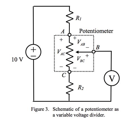
In a potentiometer circuit, the potentiometer is connected as a voltage divider. A voltage divider is a simple circuit that splits a voltage into smaller parts using two or more resistors connected in series. The input voltage is applied across the entire resistive element of the potentiometer, and the output voltage is taken from the wiper terminal.
As the wiper moves along the resistive element, it changes the ratio of resistance between the wiper and the two end terminals. This change in resistance causes a change in the output voltage, which can be calculated using the voltage divider formula:
Vout = Vin × (R2 / (R1 + R2))
Where:
– Vout is the output voltage
– Vin is the input voltage
– R1 is the resistance between the wiper and one end terminal
– R2 is the resistance between the wiper and the other end terminal
By adjusting the position of the wiper, the output voltage can be varied between 0 volts and the input voltage. This allows for precise control of the output voltage, making potentiometer circuits ideal for a wide range of applications.

Types of Potentiometers
There are several types of potentiometers available, each with its own unique characteristics and applications. The most common types include:
-
Linear Potentiometers: These potentiometers have a resistive element with a uniform cross-section, resulting in a linear relationship between the wiper position and the resistance. Linear potentiometers are commonly used in audio equipment, lighting control, and Sensor Circuits.
-
Logarithmic Potentiometers: Also known as audio taper potentiometers, these have a resistive element with a non-uniform cross-section. The resistance change is logarithmic, which is suitable for applications requiring a non-linear response, such as volume control in audio systems.
-
Rotary Potentiometers: These potentiometers have a circular resistive element and a rotating wiper. They are available in both linear and logarithmic tapers and are commonly used in control panels, instrument panels, and as position sensors.
-
Slide Potentiometers: Also called slider potentiometers, these have a linear resistive element and a sliding wiper. They are often used in mixing consoles, lighting control panels, and graphic equalizers.
-
Digital Potentiometers: These are electronically controlled potentiometers that use digital signals to set the wiper position. They offer high precision, low noise, and can be controlled by microcontrollers or digital systems. Digital potentiometers are used in automatic calibration, signal conditioning, and programmable gain amplifiers.

Applications of Potentiometer Circuits
Potentiometer circuits find applications in a wide range of industries and devices due to their simplicity, versatility, and precision. Some of the most common applications include:
-
Audio Equipment: Potentiometers are extensively used in audio equipment for volume control, tone control, and signal mixing. Logarithmic potentiometers are preferred for volume control as they provide a more natural-sounding volume adjustment.
-
Sensor Circuits: Potentiometers can be used as position sensors, where the wiper position corresponds to the physical position of an object. This is commonly used in robotics, automotive systems, and industrial automation for feedback control and position monitoring.
-
Lighting Control: Potentiometer circuits are used in lighting control systems to adjust the intensity of lights. Dimmer switches often use potentiometers to control the voltage supplied to the lights, allowing for smooth brightness control.
-
Instrumentation: In electronic test and measurement equipment, potentiometer circuits are used for calibration, offset adjustment, and signal conditioning. They allow for precise adjustment of circuit parameters to ensure accurate measurements.
-
Motor Speed Control: Potentiometer circuits can be used to control the speed of DC motors by varying the voltage supplied to the motor. This is commonly used in robotics, automotive systems, and industrial machinery.
-
Voltage Reference: Potentiometer circuits can be used to generate a stable, adjustable voltage reference for use in analog circuits. By setting the wiper position, a precise output voltage can be obtained, which is useful in calibration, signal generation, and measurement applications.

Advantages and Disadvantages of Potentiometer Circuits
Potentiometer circuits offer several advantages, making them a popular choice in many applications:
-
Simplicity: Potentiometer circuits are simple and easy to implement, requiring minimal components and design effort.
-
Versatility: Potentiometers are available in various types, sizes, and tapers, making them suitable for a wide range of applications.
-
Precision: Potentiometer circuits allow for precise control and adjustment of voltage, resistance, or position.
-
Low Cost: Potentiometers are relatively inexpensive compared to other control and measurement solutions, making them cost-effective for many applications.
However, potentiometer circuits also have some disadvantages:
-
Mechanical Wear: Potentiometers are mechanical devices and are subject to wear and tear over time. The sliding or rotating contact can cause the resistive element to degrade, affecting the accuracy and reliability of the circuit.
-
Resolution: The resolution of a potentiometer circuit is limited by the number of turns or the length of the resistive element. High-resolution applications may require more expensive, precision potentiometers.
-
Noise: The sliding or rotating contact can introduce electrical noise into the circuit, which may be problematic in sensitive analog applications.
-
Power Handling: Potentiometers have limited power handling capabilities due to the small size of the resistive element. High-power applications may require the use of external power resistors or alternative control methods.
Troubleshooting Potentiometer Circuits
When working with potentiometer circuits, some common issues may arise. Here are a few troubleshooting tips:
-
Erratic or Inconsistent Output: If the output of the potentiometer circuit is erratic or inconsistent, it may be due to a dirty or worn potentiometer. Clean the potentiometer with contact cleaner or replace it if the issue persists.
-
No Output: If there is no output from the potentiometer circuit, check the connections and ensure that the potentiometer is properly wired. Also, verify that the input voltage is present and within the specified range.
-
Limited Range: If the output voltage range is limited or not reaching the expected values, check the potentiometer’s resistance value and ensure it matches the circuit requirements. Also, verify that the input voltage is correct and the potentiometer is properly calibrated.
-
Noise: If the potentiometer circuit is introducing noise into the system, try cleaning the potentiometer or replacing it with a higher-quality component. In some cases, adding a small capacitor across the potentiometer terminals can help filter out the noise.
Frequently Asked Questions
Q1. What is the difference between a potentiometer and a rheostat?
A1. A potentiometer is a three-terminal device used as a voltage divider, while a rheostat is a two-terminal device used to control current. Potentiometers have a wiper terminal that allows for variable voltage output, whereas rheostats have a single adjustable resistance.
Q2. Can a potentiometer be used as a variable resistor?
A2. Yes, a potentiometer can be used as a variable resistor by connecting one end terminal and the wiper terminal, effectively creating a two-terminal device with adjustable resistance.
Q3. What is the power rating of a potentiometer?
A3. The power rating of a potentiometer depends on its size and construction. Smaller potentiometers typically have power ratings of 0.125 W to 0.5 W, while larger potentiometers can handle up to several watts. It is essential to choose a potentiometer with an appropriate power rating for the application to avoid damage or failure.
Q4. How do I choose the right taper for my potentiometer?
A4. The choice of taper depends on the application. For audio volume control, logarithmic (audio) taper potentiometers are preferred as they provide a more natural-sounding volume adjustment. For most other applications, linear taper potentiometers are suitable as they provide a linear relationship between wiper position and resistance.
Q5. Can I use a potentiometer for high-frequency applications?
A5. Potentiometers are not ideal for high-frequency applications due to their inherent inductance and capacitance. At high frequencies, these parasitic effects can cause signal distortion and attenuation. For high-frequency applications, it is better to use specialized variable resistors or digital control methods.
| Potentiometer Type | Taper | Applications |
|---|---|---|
| Linear | Linear | Audio equipment, lighting control, sensor circuits |
| Logarithmic | Audio | Volume control in audio systems |
| Rotary | Linear/Audio | Control panels, instrument panels, position sensors |
| Slide | Linear | Mixing consoles, lighting control panels, graphic equalizers |
| Digital | N/A | Automatic calibration, signal conditioning, programmable gain amplifiers |
Conclusion
Potentiometer circuits are versatile and essential components in many electronic devices, offering precise control and measurement of voltage, resistance, and position. By understanding the working principles, types, and applications of potentiometer circuits, engineers and technicians can effectively design, troubleshoot, and maintain systems that rely on these components.
As technology advances, potentiometer circuits continue to find new applications in emerging fields such as robotics, automotive electronics, and IoT devices. While they may face challenges in high-frequency and high-power applications, potentiometer circuits remain a reliable and cost-effective solution for a wide range of control and measurement tasks.
By mastering the fundamentals of potentiometer circuits and staying updated with the latest developments in the field, professionals can create innovative and efficient electronic systems that meet the ever-growing demands of modern technology.
No responses yet