Introduction to NanoBoard 3000
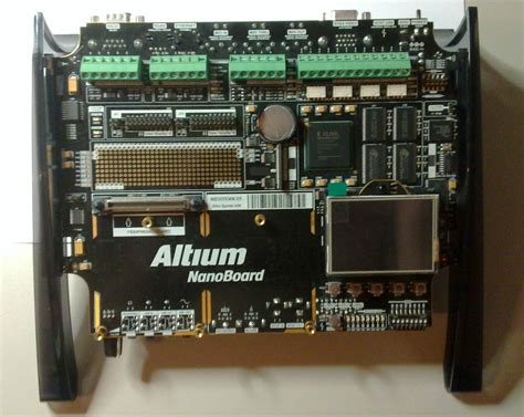
The NanoBoard 3000 is a powerful development board designed for prototyping and implementing complex digital systems. It features a high-performance Xilinx Spartan-3 FPGA (Field Programmable Gate Array) which allows users to create custom hardware designs. One of the key components of the NanoBoard 3000 is the SD Card Reader, which enables data storage and retrieval using an SD card.
Key Features of NanoBoard 3000
| Feature | Description |
|---|---|
| Xilinx Spartan-3 FPGA | XC3S1500-4FG676 with 1.5 million system gates |
| On-board Memory | 64MB SDRAM, 16MB Intel StrataFlash Flash |
| USB 2.0 Interface | High-speed USB 2.0 for programming and data transfer |
| Expansion Connectors | Two 50-pin expansion connectors for custom interfaces |
| SD Card Reader | Supports SD and MMC cards up to 2GB |
| User LEDs and Switches | 8 user LEDs and 4 user switches for input/output |
| Power Supply | 5V DC input or USB powered |
Understanding the SD Card Reader
The SD Card Reader on the NanoBoard 3000 allows users to store and retrieve data using an SD (Secure Digital) card. SD cards are widely used in various electronic devices, such as digital cameras, smartphones, and embedded systems, due to their compact size, high storage capacity, and reliability.
SD Card Basics
SD cards come in different sizes and capacities, ranging from a few megabytes to several gigabytes. They use a standard interface for communication, which includes the following pins:
| Pin | Name | Description |
|---|---|---|
| 1 | CD/DAT3 | Card Detect / Data Line 3 |
| 2 | CMD | Command Line |
| 3 | VSS | Ground |
| 4 | VDD | Supply Voltage |
| 5 | CLK | Clock |
| 6 | VSS | Ground |
| 7 | DAT0 | Data Line 0 |
| 8 | DAT1 | Data Line 1 |
| 9 | DAT2 | Data Line 2 |
The SD card communicates with the host device using a simple protocol that involves sending commands and receiving responses. The host device can read and write data to the card using block-level access.
Interfacing SD Card with FPGA
To use the SD Card Reader on the NanoBoard 3000, you need to implement an SD card controller in the FPGA. The controller handles the low-level communication with the SD card, including initializing the card, sending commands, and transferring data.
The main steps involved in interfacing an SD card with the FPGA are:
- Implementing the SD card controller in the FPGA using a hardware description language (HDL) such as Verilog or VHDL.
- Connecting the SD card pins to the appropriate pins on the FPGA.
- Writing software to interact with the SD card controller and perform read/write operations.

Implementing SD Card Controller in FPGA
To implement the SD card controller in the FPGA, you can use a pre-designed IP core or create your own custom design. Many FPGA vendors, such as Xilinx and Intel (formerly Altera), provide SD card controller IP cores that can be easily integrated into your project.
If you decide to create your own SD card controller, you need to follow the SD card specification and implement the necessary state machines and data paths. The main components of an SD card controller include:
- Command generator: Generates the appropriate commands to initialize and communicate with the SD card.
- Response handler: Receives and processes the responses from the SD card.
- Data path: Handles the data transfer between the FPGA and the SD card, including buffering and error checking.
- Clock generator: Provides the necessary clock signals for the SD card and the controller.
Here’s a simplified block diagram of an SD card controller:
graph LR
A[FPGA] -- Commands --> B[Command Generator]
B -- Commands --> C[SD Card]
C -- Responses --> D[Response Handler]
D -- Status --> A
A -- Data --> E[Data Path]
E -- Data --> C
F[Clock Generator] -- Clock --> C
Verilog Example
Here’s a simple Verilog example that demonstrates the basic structure of an SD card controller:
module sd_controller (
    input wire clk,
    input wire rst,
    input wire [31:0] cmd,
    output reg [31:0] response,
    input wire [7:0] data_in,
    output reg [7:0] data_out,
    output reg data_out_valid,
    input wire data_in_valid,
    output reg busy
);

    // Command generator
    always @(posedge clk) begin
        if (rst) begin
            // Reset logic
        end else begin
            // Generate commands based on input
        end
    end

    // Response handler
    always @(posedge clk) begin
        if (rst) begin
            // Reset logic
        end else begin
            // Process responses from SD card
        end
    end

    // Data path
    always @(posedge clk) begin
        if (rst) begin
            // Reset logic
        end else begin
            // Handle data transfer between FPGA and SD card
        end
    end

endmodule
This example shows the basic structure of an SD card controller with separate always blocks for the command generator, response handler, and data path. You would need to expand on this basic structure to implement the full functionality of the SD card controller according to the SD card specification.

Software Interaction with SD Card Controller
Once you have implemented the SD card controller in the FPGA, you need to write software to interact with it and perform read/write operations on the SD card. The software runs on a processor, such as the MicroBlaze or PowerPC, which communicates with the SD card controller through memory-mapped registers or a dedicated bus interface.
The main steps involved in the software interaction with the SD card controller are:
- Initializing the SD card by sending the appropriate commands and checking the responses.
- Reading and writing data to the SD card using block-level access.
- Handling errors and exceptions that may occur during the communication with the SD card.
Here’s a simple C code example that demonstrates the basic flow of interacting with an SD card controller:
#include <stdio.h>
#include "sd_controller.h"

int main() {
    // Initialize the SD card
    if (sd_init() != SD_OK) {
        printf("SD card initialization failed!\n");
        return -1;
    }

    // Write data to the SD card
    uint8_t write_data[] = {0x01, 0x02, 0x03, 0x04};
    if (sd_write_block(0, write_data) != SD_OK) {
        printf("SD card write failed!\n");
        return -1;
    }

    // Read data from the SD card
    uint8_t read_data[4];
    if (sd_read_block(0, read_data) != SD_OK) {
        printf("SD card read failed!\n");
        return -1;
    }

    // Print the read data
    printf("Read data: ");
    for (int i = 0; i < 4; i++) {
        printf("0x%02x ", read_data[i]);
    }
    printf("\n");

    return 0;
}
In this example, the software first initializes the SD card using the sd_init() function. Then, it writes a block of data to the SD card using the sd_write_block() function and reads the same block back using the sd_read_block() function. Finally, it prints the read data to the console.
The actual implementation of the sd_init(), sd_write_block(), and sd_read_block() functions would depend on the specific SD card controller design and the interface between the processor and the controller.

Frequently Asked Questions (FAQ)
-
Q: What is the maximum capacity of SD cards supported by the NanoBoard 3000?
A: The NanoBoard 3000 supports SD and MMC cards up to 2GB in capacity. -
Q: Can I use the NanoBoard 3000 SD Card Reader with other FPGA development boards?
A: The SD Card Reader is specific to the NanoBoard 3000 and may not be directly compatible with other FPGA development boards. However, the principles and techniques used to implement the SD card controller can be applied to other boards with appropriate modifications. -
Q: Do I need to use a specific SD card format with the NanoBoard 3000?
A: The NanoBoard 3000 SD Card Reader supports standard SD and MMC card formats. It is recommended to use cards that are compatible with the SD card specification version 2.0 or later. -
Q: How do I access the data stored on the SD card from my computer?
A: To access the data stored on the SD card, you need to implement a communication interface between the FPGA and your computer. This can be done using the USB 2.0 interface provided on the NanoBoard 3000. You would need to develop software on both the FPGA and the computer to facilitate the data transfer. -
Q: Can I use the NanoBoard 3000 SD Card Reader for real-time data logging applications?
A: Yes, the NanoBoard 3000 SD Card Reader can be used for real-time data logging applications. However, the performance and reliability of the data logging would depend on factors such as the SD card write speed, the FPGA design, and the software implementation. Careful design and testing are necessary to ensure reliable data logging in real-time applications.
Conclusion
The NanoBoard 3000 SD Card Reader is a valuable resource for developers working with FPGAs and embedded systems. By utilizing the SD Card Reader, developers can store and retrieve data from an SD card, enabling data logging, configuration storage, and other applications that require non-volatile memory.
Implementing an SD card controller in the FPGA requires a good understanding of the SD card protocol and the ability to design hardware using HDL. Pre-designed IP cores can simplify the process, but custom designs offer more flexibility and control.
Software plays a crucial role in interacting with the SD card controller, initializing the card, and performing read/write operations. Careful design and testing of both the hardware and software components are essential for reliable and efficient operation of the SD Card Reader.
The NanoBoard 3000 SD Card Reader, combined with the powerful Xilinx Spartan-3 FPGA, provides a versatile platform for prototyping and implementing complex digital systems with data storage capabilities.

No responses yet