Understanding PCB Ringing and Its Impact on Signal Integrity
PCB ringing is a common issue that can significantly impact the signal integrity of a printed circuit board (PCB). It occurs when a signal experiences unwanted oscillations or overshoots, leading to distortions and potential malfunctions in the electronic system. In this comprehensive article, we will delve into the causes of PCB ringing, its effects on signal quality, and effective strategies to mitigate this problem.
What is PCB Ringing?
PCB ringing, also known as signal ringing or overshoot, refers to the undesired oscillations that occur when a signal transitions from one state to another. These oscillations are typically observed as a series of diminishing peaks and troughs following the initial signal transition. Ringing can introduce noise, cause signal distortions, and lead to timing issues in digital circuits.
The Importance of Addressing PCB Ringing
Maintaining signal integrity is crucial for the proper functioning and reliability of electronic systems. PCB ringing can have several detrimental effects:
- Signal Distortion: Ringing can distort the shape of the signal, making it difficult for receivers to interpret the intended information accurately.
- Timing Issues: Excessive ringing can introduce timing uncertainties, leading to synchronization problems in digital circuits.
- Electromagnetic Interference (EMI): Ringing can generate unwanted high-frequency components that contribute to EMI, potentially interfering with nearby electronic devices.
- Reduced System Reliability: Signal integrity issues caused by ringing can compromise the overall reliability and performance of the electronic system.
Causes of PCB Ringing
To effectively address PCB ringing, it is essential to understand its underlying causes. Several factors can contribute to the occurrence of ringing on a PCB:
Impedance Mismatch
Impedance mismatch is a primary cause of PCB ringing. When a signal encounters a change in impedance along its transmission path, a portion of the signal energy is reflected back, leading to reflections and ringing. This mismatch can occur due to:
- Improper termination of transmission lines
- Inconsistent characteristic impedance of PCB traces
- Abrupt changes in trace width or thickness
- Inadequate impedance matching at connectors or interfaces
Excessive Trace Inductance
PCB traces exhibit inherent inductance, which can contribute to ringing. Factors that increase trace inductance include:
- Long trace lengths
- Narrow trace widths
- Inadequate ground plane coverage
- Insufficient via usage for ground connections
Capacitive Loading
Capacitive loading occurs when a signal trace is loaded with excessive capacitance, such as from:
- Unterminated or improperly terminated stubs
- Large component packages with significant input capacitance
- Closely spaced parallel traces causing mutual capacitance
Capacitive loading can lead to signal reflections and ringing, especially at high frequencies.
Signal Integrity Analysis Techniques
To identify and quantify PCB ringing, several signal integrity analysis techniques can be employed:
| Technique | Description |
|---|---|
| Time-Domain Reflectometry (TDR) | Sends a fast-rising pulse through the signal path and measures reflections to locate impedance discontinuities. |
| Frequency-Domain Reflectometry (FDR) | Measures the frequency response of the signal path to identify resonances and impedance mismatches. |
| Eye Diagram Analysis | Overlays multiple signal transitions to assess signal quality, including ringing, jitter, and noise margin. |
| Simulation and Modeling | Uses computer-aided design (CAD) tools to simulate and predict signal behavior, allowing for pre-layout analysis and optimization. |
Strategies to Mitigate PCB Ringing
Mitigating PCB ringing requires a combination of design techniques and best practices. Here are some effective strategies to minimize ringing and improve signal integrity:
Impedance Matching and Controlled Impedance Design
Ensuring proper impedance matching throughout the signal path is crucial to minimize reflections and ringing. This involves:
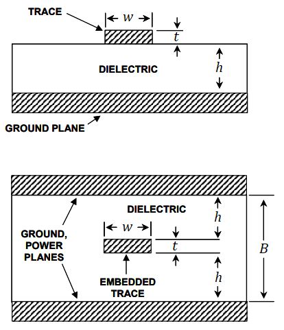
- Calculating and designing PCB traces with consistent characteristic impedance
- Using controlled impedance techniques, such as stripline or microstrip, to maintain impedance uniformity
- Matching the impedance of components, connectors, and terminations to the characteristic impedance of the traces
Termination Techniques
Proper termination of transmission lines helps absorb reflections and minimize ringing. Common termination techniques include:
- Series termination: Adding a resistor in series with the driver to match the characteristic impedance of the trace
- Parallel termination: Placing a resistor at the end of the trace to match the characteristic impedance
- Thevenin and AC termination: Using a combination of resistors and capacitors for more advanced termination schemes
Optimizing Trace Geometry and Routing
Careful design of trace geometry and routing can help reduce inductance and minimize ringing:
- Keep trace lengths as short as possible to reduce overall inductance
- Use wider traces to decrease inductance and improve current-carrying capacity
- Provide adequate ground plane coverage to minimize loop inductance
- Use ground vias strategically to create low-impedance return paths
Managing Capacitive Loading
To minimize the impact of capacitive loading on signal integrity:
- Avoid unterminated or poorly terminated stubs
- Choose components with lower input capacitance when possible
- Increase the spacing between parallel traces to reduce mutual capacitance
- Use ground shields or guard traces to isolate sensitive signals from capacitive coupling
Filtering and Damping Techniques
In some cases, additional filtering and damping techniques can be employed to suppress ringing:
- Add series resistors or ferrite beads to damp high-frequency oscillations
- Implement RC or LC filters to attenuate specific frequency ranges
- Use snubber circuits or clamping diodes to limit overshoot and undershoot
Simulation and Pre-Layout Analysis
Performing simulation and pre-layout analysis using CAD tools can help identify potential ringing issues early in the design process. This allows for proactive optimization of trace routing, impedance matching, and component placement before committing to the physical layout.

Frequently Asked Questions (FAQ)
-
What is the main cause of PCB ringing?
The main cause of PCB ringing is impedance mismatch along the signal transmission path. When a signal encounters a change in impedance, a portion of the signal energy is reflected back, leading to oscillations and ringing. -
How does PCB ringing affect signal integrity?
PCB ringing can distort the shape of the signal, making it difficult for receivers to interpret the intended information accurately. It can also introduce timing uncertainties, leading to synchronization issues in digital circuits. Additionally, ringing can generate unwanted high-frequency components that contribute to electromagnetic interference (EMI). -
What are some effective strategies to mitigate PCB ringing?
Effective strategies to mitigate PCB ringing include: - Ensuring proper impedance matching throughout the signal path
- Using controlled impedance techniques for PCB trace design
- Employing appropriate termination techniques, such as series or parallel termination
- Optimizing trace geometry and routing to minimize inductance
- Managing capacitive loading by avoiding unterminated stubs and increasing trace spacing
-
Applying filtering and damping techniques, such as series resistors or RC filters
-
How can simulation and pre-layout analysis help in addressing PCB ringing?
Simulation and pre-layout analysis using CAD tools allow designers to identify potential ringing issues early in the design process. By simulating signal behavior and analyzing impedance discontinuities, designers can proactively optimize trace routing, impedance matching, and component placement before finalizing the physical layout. This helps in minimizing ringing and improving overall signal integrity. -
What are some common signal integrity analysis techniques used to identify PCB ringing?
Common signal integrity analysis techniques used to identify PCB ringing include: - Time-Domain Reflectometry (TDR): Sends a fast-rising pulse through the signal path and measures reflections to locate impedance discontinuities.
- Frequency-Domain Reflectometry (FDR): Measures the frequency response of the signal path to identify resonances and impedance mismatches.
- Eye Diagram Analysis: Overlays multiple signal transitions to assess signal quality, including ringing, jitter, and noise margin.
- Simulation and Modeling: Uses computer-aided design (CAD) tools to simulate and predict signal behavior, allowing for pre-layout analysis and optimization.
Conclusion
PCB ringing is a critical signal integrity issue that can significantly impact the performance and reliability of electronic systems. By understanding the causes of ringing, such as impedance mismatch, excessive trace inductance, and capacitive loading, designers can take proactive steps to mitigate this problem.
Effective strategies for minimizing PCB ringing include proper impedance matching, controlled impedance design, appropriate termination techniques, optimized trace geometry and routing, and management of capacitive loading. Additionally, employing signal integrity analysis techniques and leveraging simulation and pre-layout analysis tools can help identify and address ringing issues early in the design process.
By implementing these best practices and techniques, designers can ensure the signal integrity of their PCBs, minimize signal distortions, and improve the overall performance and reliability of electronic systems. Addressing PCB ringing is an essential aspect of high-quality PCB design and is crucial for meeting the demands of today’s advanced electronic applications.
No responses yet