Introduction to Transmission Lines and Waveforms
Transmission lines are essential for transmitting electrical signals over distances. They consist of two or more parallel conductors that guide electromagnetic waves from a source to a load. The behavior of voltage and current waveforms on transmission lines depends on the line’s characteristics such as impedance, length, and termination.
One important case is a series terminated transmission line, where the load impedance matches the characteristic impedance of the line. This termination prevents reflections and ensures maximum power transfer to the load. Understanding the voltage and current waveforms is crucial for designing and analyzing transmission line systems.
Characteristic Impedance and Propagation Constant
The characteristic impedance (Z0) and propagation constant (γ) are two fundamental parameters that describe a transmission line’s properties. The characteristic impedance relates the voltage and current waves traveling along the line in the same direction. It depends on the line’s geometry and the surrounding medium.
For a lossless line, the characteristic impedance is given by:
Z0 = √(L/C)
where L is the inductance per unit length and C is the capacitance per unit length.
The propagation constant determines how the wave’s amplitude and phase change as it travels down the line. For a lossless line, the propagation constant is purely imaginary and is given by:
γ = jβ = jω√(LC)
where ω is the angular frequency, and β is the phase constant.

Voltage and Current Waveforms in Time Domain
Let’s consider a series terminated lossless transmission line with a characteristic impedance Z0, driven by a voltage source vs(t) with a source impedance Rs equal to Z0. The load impedance RL is also equal to Z0.
The voltage and current at any point x along the line and at any time t are given by:
v(x,t) = v+(x,t) + v-(x,t)
i(x,t) = [v+(x,t) – v-(x,t)]/Z0
where v+(x,t) and v-(x,t) are the forward and backward traveling voltage waves, respectively.
For a series terminated line, there are no reflections from the load. The forward traveling wave is the incident wave from the source, while the backward traveling wave is zero. Therefore,
v+(x,t) = vs(t – x/vp)
v-(x,t) = 0
where vp is the phase velocity of the wave, given by:
vp = 1/√(LC)
The voltage and current waveforms along the line are:
v(x,t) = vs(t – x/vp)
i(x,t) = vs(t – x/vp)/Z0
At the source (x=0), the voltage and current are:
v(0,t) = vs(t)
i(0,t) = vs(t)/Z0
At the load (x=l, where l is the length of the line), the voltage and current are:
v(l,t) = vs(t – l/vp)
i(l,t) = vs(t – l/vp)/Z0
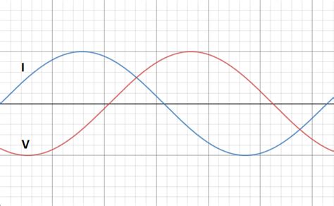
The waveforms are delayed versions of the source voltage, with the delay determined by the line length and phase velocity. The current waveform is a scaled version of the voltage waveform, with the scaling factor being the reciprocal of the characteristic impedance.

Voltage and Current Waveforms in Frequency Domain
In the frequency domain, the voltage and current waves can be represented using phasors. The phasor representation assumes a steady-state sinusoidal excitation.
Let the source voltage be:
Vs(ω) = V+s exp(jωt)
where V+s is the amplitude of the source voltage phasor.
The forward and backward traveling voltage phasors are:
V+(x) = V+s exp(-γx)
V-(x) = 0
The voltage and current phasors along the line are:
V(x) = V+s exp(-γx)
I(x) = V+s exp(-γx)/Z0
At the source (x=0), the voltage and current phasors are:
V(0) = V+s
I(0) = V+s/Z0
At the load (x=l), the voltage and current phasors are:
V(l) = V+s exp(-γl)
I(l) = V+s exp(-γl)/Z0
The phasor representation provides insight into the amplitude and phase relationships between the voltage and current waves at different points along the line.

Standing Wave Patterns
In a series terminated line, there are no reflections from the load, and thus no standing waves are formed. The voltage and current amplitudes remain constant along the line, with only a phase shift determined by the propagation constant.
The voltage and current standing wave ratios (VSWR and ISWR) are unity for a series terminated line, indicating a perfect match between the line and the load.
VSWR = ISWR = 1
Power Transfer and Efficiency
In a series terminated line, the load impedance matches the characteristic impedance of the line, ensuring maximum power transfer from the source to the load. The power delivered to the load is given by:
PL = |V+s|^2/(2Z0)
The power efficiency, defined as the ratio of the power delivered to the load to the power supplied by the source, is 100% for a lossless series terminated line.
Efficiency = PL/Ps = 1
Transient Response
When a transmission line is excited by a non-sinusoidal source, such as a step or pulse, the waveforms exhibit a transient response. The transient behavior depends on the line’s characteristics and the source waveform.
For a series terminated line excited by a step voltage with an amplitude Vs, the voltage and current waveforms are:
v(x,t) = Vs [u(t – x/vp) – u(t – (2l – x)/vp)]
i(x,t) = (Vs/Z0) [u(t – x/vp) – u(t – (2l – x)/vp)]
where u(t) is the unit step function.
The waveforms consist of a forward traveling step wave and a backward traveling step wave that cancels the forward wave after one round trip delay (2l/vp). The resulting waveforms are a single step delayed by the propagation time from the source to the observation point.
Applications
Series terminated transmission lines find applications in various fields, including:
-
High-speed digital communication: Series termination is used in digital signaling to minimize reflections and improve signal integrity.
-
Pulse generation and shaping: Series terminated lines can shape pulses by controlling the line length and characteristic impedance.
-
Impedance matching: Series termination provides a simple way to match the source impedance to the line impedance, maximizing power transfer and minimizing reflections.
-
Transmission line measurements: Series terminated lines are used in time-domain reflectometry (TDR) to characterize transmission line parameters and locate discontinuities.
Conclusion
Understanding voltage and current waveforms in series terminated transmission lines is essential for designing and analyzing high-speed communication systems, pulse shaping circuits, and impedance matching networks. By matching the load impedance to the characteristic impedance of the line, series termination eliminates reflections and ensures maximum power transfer. The waveforms can be analyzed in both the time and frequency domains, providing insight into the propagation, delay, and transient behavior of signals on the line.
FAQ
What is a series terminated transmission line?
A series terminated transmission line is a transmission line where the load impedance is equal to the characteristic impedance of the line. This termination prevents reflections from the load and ensures maximum power transfer.
How do you calculate the characteristic impedance of a transmission line?
For a lossless transmission line, the characteristic impedance is given by Z0 = √(L/C), where L is the inductance per unit length and C is the capacitance per unit length. These parameters depend on the line’s geometry and the surrounding medium.
What is the propagation constant of a lossless transmission line?
The propagation constant of a lossless transmission line is purely imaginary and is given by γ = jβ = jω√(LC), where ω is the angular frequency, and β is the phase constant. It determines how the wave’s amplitude and phase change as it travels along the line.
How do you calculate the power delivered to the load in a series terminated line?
The power delivered to the load in a series terminated line is given by PL = |V+s|^2/(2Z0), where V+s is the amplitude of the forward traveling voltage wave, and Z0 is the characteristic impedance of the line.
What is the voltage standing wave ratio (VSWR) in a series terminated line?
The voltage standing wave ratio (VSWR) in a series terminated line is unity (VSWR = 1), indicating a perfect match between the line and the load. There are no standing waves on the line, and the voltage amplitude remains constant along the line.

No responses yet