Step 1: Choose Your Temperature Sensor
The first step in designing your PCB thermometer is selecting an appropriate temperature sensor. There are several types of temperature sensors available, each with its own advantages and disadvantages. Here are some popular options:
| Sensor Type | Advantages | Disadvantages |
|---|---|---|
| Thermistor | – High sensitivity – Fast response time – Low cost |
– Non-linear output – Limited temperature range |
| RTD (Resistance Temperature Detector) | – High accuracy – Excellent stability – Wide temperature range |
– Higher cost than thermistors – Slower response time |
| Thermocouple | – Wide temperature range – Rugged and durable – Suitable for harsh environments |
– Requires cold junction compensation – Lower accuracy than RTDs |
| Digital Temperature Sensor (e.g., DS18B20) | – Digital output – Easy to interface with microcontrollers – Good accuracy |
– Requires digital communication protocol – Limited temperature range compared to thermocouples |
For this project, we will use a digital temperature sensor, specifically the DS18B20, due to its ease of use and digital output.
Step 2: Select a Microcontroller
To process the temperature data from the sensor and display it on an LCD or other display, you’ll need a microcontroller. Some popular options include:
- Arduino (e.g., Arduino Uno, Arduino Nano)
- PIC microcontrollers
- AVR microcontrollers (e.g., ATmega328)
For this project, we will use an Arduino Nano due to its small size and ease of programming.

Step 3: Design the Schematic
Once you have selected your temperature sensor and microcontroller, it’s time to design the schematic for your PCB thermometer. The schematic is a diagram that shows how the components are connected electrically. Here’s a basic schematic for our PCB thermometer:
[Insert schematic image here]
The schematic includes the following components:
– Arduino Nano microcontroller
– DS18B20 temperature sensor
– 4.7k pull-up resistor for the DS18B20
– 16×2 LCD display
– 10k potentiometer for LCD contrast adjustment
– 220Ω resistor for LCD backlight control

Step 4: Design the PCB Layout
With the schematic complete, you can now design the PCB layout. The PCB layout is a physical representation of the schematic, showing where components are placed and how they are connected with traces. To design the PCB layout, you can use PCB design software such as KiCad, Eagle, or Altium Designer.
Here are some tips for designing your PCB layout:
– Keep the temperature sensor away from heat-generating components like voltage regulators or power traces.
– Use wide traces for power supply and ground connections to minimize resistance and ensure reliable operation.
– Include mounting holes for easy installation of your finished PCB thermometer.
– Follow good PCB design practices, such as minimizing trace lengths, avoiding sharp angles, and providing proper grounding.

Step 5: Manufacture the PCB
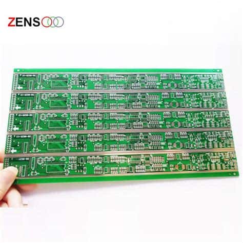
Once your PCB layout is complete, you’ll need to manufacture the physical PCB. You have several options:
-
DIY PCB fabrication: If you have access to a CNC machine or chemical etching equipment, you can make your own PCBs at home. This can be a fun and educational process but requires some specialized tools and skills.
-
PCB Prototyping services: Many online PCB manufacturers offer prototyping services for small-batch PCBs. You simply upload your PCB design files (usually Gerber files), and they’ll manufacture the boards for you. Some popular PCB prototyping services include:
- JLCPCB
- PCBWay
- OSH Park
For this project, we’ll use a PCB prototyping service for convenience and professional-quality results.
Step 6: Assemble the Components
After receiving your manufactured PCB, it’s time to assemble the components. You’ll need to solder the components onto the PCB according to the schematic and PCB layout.
Here are some tips for successful soldering:
– Use a temperature-controlled soldering iron with a fine tip for precise soldering.
– Apply a small amount of solder to the pad and the component lead simultaneously to create a strong joint.
– Use flux to help the solder flow and create cleaner joints.
– Inspect your solder joints for any bridges, cold joints, or insufficient solder.
Step 7: Program and Test Your PCB Thermometer
With the components assembled, you can now program your Arduino Nano and test your PCB thermometer. Here’s a sample Arduino sketch for reading the temperature from the DS18B20 sensor and displaying it on the LCD:
#include <OneWire.h>
#include <DallasTemperature.h>
#include <LiquidCrystal.h>

#define ONE_WIRE_BUS 2 // Data wire connected to Arduino pin 2

OneWire oneWire(ONE_WIRE_BUS);
DallasTemperature sensors(&oneWire);
LiquidCrystal lcd(12, 11, 5, 4, 3, 2); // RS, E, D4, D5, D6, D7

void setup() {
  lcd.begin(16, 2);
  sensors.begin();
}

void loop() {
  sensors.requestTemperatures();
  float temperature = sensors.getTempCByIndex(0);

  lcd.setCursor(0, 0);
  lcd.print("Temp: ");
  lcd.print(temperature);
  lcd.print(" C");

  delay(1000);
}
Upload this sketch to your Arduino Nano and power on your PCB thermometer. The LCD should display the current temperature reading from the DS18B20 sensor. If the temperature reading is incorrect or the LCD doesn’t display anything, double-check your solder joints and component connections.
Frequently Asked Questions (FAQ)
-
Q: Can I use a different temperature sensor instead of the DS18B20?
A: Yes, you can use other temperature sensors like thermistors, RTDs, or thermocouples. However, you’ll need to modify the schematic and Arduino code accordingly. -
Q: How accurate is the DS18B20 temperature sensor?
A: The DS18B20 has an accuracy of ±0.5°C in the range of -10°C to +85°C. For most applications, this is sufficient. If you need higher accuracy, consider using an RTD or a more precise digital sensor. -
Q: Can I add features like temperature logging or alarms to my PCB thermometer?
A: Yes, you can extend the functionality of your PCB thermometer by modifying the Arduino code. For example, you can add an SD card module to log temperature data over time or include a buzzer to sound an alarm when the temperature exceeds a certain threshold. -
Q: How can I power my PCB thermometer?
A: You can power your PCB thermometer using a variety of methods, such as: - USB power from the Arduino Nano
- Battery power (e.g., 9V battery or rechargeable Li-ion battery)
-
DC power supply (e.g., wall adapter)
-
Q: Can I use this PCB thermometer for measuring body temperature?
A: While the DS18B20 is capable of measuring temperatures in the range of human body temperature, it is not recommended to use this PCB thermometer for medical purposes without proper calibration and certification. For measuring body temperature, use a dedicated medical-grade thermometer.
Conclusion
Designing a PCB thermometer can be a fun and educational project for electronics enthusiasts. By following these 7 steps, you can create your own functional digital thermometer:
- Choose your temperature sensor
- Select a microcontroller
- Design the schematic
- Design the PCB layout
- Manufacture the PCB
- Assemble the components
- Program and test your PCB thermometer
Through this process, you’ll gain valuable skills in PCB design, component selection, soldering, and programming. Don’t be discouraged if you encounter challenges along the way – troubleshooting and problem-solving are essential parts of the learning process.
Once you’ve successfully built your PCB thermometer, you can explore further improvements and modifications, such as adding features like temperature logging, alarms, or wireless connectivity. The possibilities are endless!
So, grab your tools, fire up your PCB design software, and start building your own PCB thermometer today. Happy designing and soldering!

No responses yet