Introduction to 7-Segment Displays
A 7-segment display is an electronic device that is commonly used to display numerical information. It consists of seven segments, each of which can be illuminated to form the digits 0 through 9. The segments are typically arranged in a figure-8 pattern, with the top and bottom segments being horizontal and the remaining segments being vertical.
7-segment displays are widely used in a variety of applications, including:
- Digital clocks and watches
- Calculators
- Appliances (e.g., microwaves, ovens)
- Instrumentation panels (e.g., in vehicles, industrial equipment)
- Scoreboards and timing displays
Types of 7-Segment Displays
There are two main types of 7-segment displays:
-
Common Cathode (CC): In a common cathode display, all the cathodes of the LED segments are connected together and grounded, while the anodes are individually controlled.
-
Common Anode (CA): In a common anode display, all the anodes of the LED segments are connected together and driven by a positive voltage, while the cathodes are individually controlled.
The choice between common cathode and common anode depends on the specific application and the driving circuitry being used.
How 7-Segment Displays Work
Basic Principle
A 7-segment display works by selectively illuminating different combinations of segments to form the desired digit. Each segment is typically made up of a light-emitting diode (LED), although other technologies such as liquid crystal displays (LCDs) and vacuum fluorescent displays (VFDs) can also be used.
To display a particular digit, the appropriate segments are turned on while the others remain off. For example, to display the digit “7”, segments a, b, and c would be illuminated, while segments d, e, f, and g would remain off.
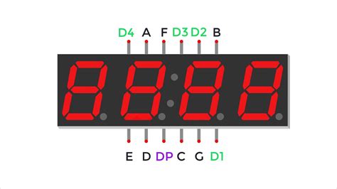
Segment Labeling
The segments in a 7-segment display are labeled with lowercase letters a through g, as shown in the following diagram:
 __a__
|     |
f     b
|__g__|
|     |
e     c
|__d__|
By convention, the decimal point (DP) is labeled with the letter “h” or “dp”.
Driving a 7-Segment Display
To control a 7-segment display, a microcontroller or dedicated driver IC is typically used. The driving circuitry is responsible for turning the appropriate segments on or off based on the desired digit to be displayed.
For a common cathode display, the driving circuitry would work as follows:
- The common cathode is connected to ground.
- To turn on a segment, a positive voltage is applied to its corresponding anode through a current-limiting resistor.
- To turn off a segment, its anode is connected to ground or left floating.
For a common anode display, the driving circuitry would work as follows:
- The common anode is connected to a positive voltage.
- To turn on a segment, its corresponding cathode is connected to ground through a current-limiting resistor.
- To turn off a segment, its cathode is connected to the positive voltage or left floating.
Multiplexing
When driving multiple 7-segment displays, a technique called multiplexing is often used to reduce the number of pins required on the driving circuitry. In a multiplexed setup, the anodes (for common cathode) or cathodes (for common anode) of corresponding segments in each display are connected together, and the common electrode of each display is individually controlled.
To display different digits on each display, the driving circuitry rapidly switches between the displays, turning on the appropriate segments for each one in turn. The switching occurs fast enough that the human eye perceives all the displays as being on simultaneously, thanks to the persistence of vision.

Interfacing with a 7-Segment Display
Using a Microcontroller
One common way to interface with a 7-segment display is by using a microcontroller, such as an Arduino. The microcontroller can be programmed to send the appropriate signals to the display based on the desired digit to be shown.
To interface a common cathode display with an Arduino, the following steps can be followed:
- Connect the common cathode to ground.
- Connect each segment’s anode to a digital output pin on the Arduino through a current-limiting resistor (typically 220-1kΩ).
- In the Arduino sketch, define which pins are connected to each segment.
- To display a digit, set the appropriate pins HIGH to turn on the corresponding segments, and set the remaining pins LOW to turn off the other segments.
For example, to display the digit “7” on a common cathode display connected to pins 2-8 on an Arduino, the following code could be used:
// Define segment pins
const int a = 2;
const int b = 3;
const int c = 4;
const int d = 5;
const int e = 6;
const int f = 7;
const int g = 8;

void setup() {
  // Set segment pins as outputs
  pinMode(a, OUTPUT);
  pinMode(b, OUTPUT);
  pinMode(c, OUTPUT);
  pinMode(d, OUTPUT);
  pinMode(e, OUTPUT);
  pinMode(f, OUTPUT);
  pinMode(g, OUTPUT);
}

void loop() {
  // Display digit 7
  digitalWrite(a, HIGH);
  digitalWrite(b, HIGH);
  digitalWrite(c, HIGH);
  digitalWrite(d, LOW);
  digitalWrite(e, LOW);
  digitalWrite(f, LOW);
  digitalWrite(g, LOW);
}
Using a Dedicated Driver IC
Another option for interfacing with a 7-segment display is to use a dedicated driver IC, such as the MAX7219 or TM1637. These ICs are specifically designed to control multiple 7-segment displays and often support features like multiplexing and brightness control.
Using a dedicated driver IC can simplify the interfacing process and reduce the number of pins required on the microcontroller. The specific interfacing details will depend on the chosen driver IC and its communication protocol (e.g., SPI, I2C).

Common 7-Segment Display Applications
Digital Clocks and Watches
One of the most common applications of 7-segment displays is in digital clocks and watches. In these devices, multiple 7-segment displays are used to show the hours, minutes, and sometimes seconds. The displays are typically driven by a dedicated clock circuit or a microcontroller that keeps track of the time and updates the display accordingly.
Calculators and Other Electronic Devices
7-segment displays are also commonly used in calculators, multimeters, and other electronic devices that need to display numerical information. In these applications, the displays are often driven by a microcontroller or dedicated driver IC that processes the data to be displayed and sends the appropriate signals to the segments.
Instrumentation Panels
In vehicles, industrial equipment, and other instrumentation panels, 7-segment displays are often used to show numerical values such as speed, temperature, or pressure. These displays are typically part of a larger system that includes sensors, processing units, and other components.
Scoreboards and Timing Displays
7-segment displays are also used in scoreboards and timing displays for sports events, races, and other competitions. In these applications, the displays are often much larger than those used in personal electronic devices and may be driven by specialized control systems.

Advantages and Disadvantages of 7-Segment Displays
Advantages
- Easy to read: 7-segment displays provide a clear, easily readable output for numerical information.
- Low power consumption: LED-based 7-segment displays have relatively low power requirements compared to other display technologies.
- Durable: 7-segment displays, particularly those based on LEDs, are typically robust and have a long lifespan.
- Customizable: The appearance of a 7-segment display can be customized by using different colored LEDs or by adding colored filters.
Disadvantages
- Limited character set: 7-segment displays are primarily designed for displaying digits and a few special characters (e.g., “-“, “E”). They are not suitable for displaying text or complex graphics.
- Increased complexity for multiple displays: When using multiple 7-segment displays, the driving circuitry becomes more complex, often requiring multiplexing or dedicated driver ICs.
- Potential for uneven brightness: If the current-limiting resistors for each segment are not well-matched, some segments may appear brighter or dimmer than others.
FAQ
- What is the difference between a common cathode and common anode 7-segment display?
-
In a common cathode display, the cathodes of all segments are connected together and grounded, while the anodes are individually controlled. In a common anode display, the anodes of all segments are connected together and driven by a positive voltage, while the cathodes are individually controlled.
-
How do I control multiple 7-segment displays with a microcontroller?
-
To control multiple 7-segment displays with a microcontroller, you can use a technique called multiplexing. This involves connecting the anodes (for common cathode) or cathodes (for common anode) of corresponding segments in each display together and individually controlling the common electrode of each display. The microcontroller rapidly switches between the displays, turning on the appropriate segments for each one in turn.
-
What is the purpose of the current-limiting resistors when interfacing with a 7-segment display?
-
Current-limiting resistors are used to protect the LEDs in the 7-segment display from excessive current, which could cause damage. The resistor value is chosen based on the LED’s forward voltage and the desired brightness.
-
Can I use a 7-segment display to show text or graphics?
-
7-segment displays are primarily designed for displaying digits and a few special characters. They are not suitable for displaying text or complex graphics. For such applications, other display technologies like LCDs or OLEDs are more appropriate.
-
Are there any alternatives to 7-segment displays for showing numerical information?
- Yes, there are several alternatives to 7-segment displays for showing numerical information, including:
- LCD (Liquid Crystal Display): LCDs can display digits, text, and simple graphics.
- OLED (Organic Light-Emitting Diode): OLEDs offer high contrast, wide viewing angles, and the ability to display text and graphics.
- VFD (Vacuum Fluorescent Display): VFDs provide bright, high-contrast displays and can show digits, text, and simple graphics.
- Dot-matrix displays: These displays consist of a matrix of LEDs or LCDs and can display digits, text, and simple graphics.
Conclusion
7-segment displays are a simple and effective way to display numerical information in a wide range of electronic devices. By selectively illuminating different combinations of segments, these displays can form the digits 0 through 9 and a few special characters.
Understanding how 7-segment displays work and how to interface with them using microcontrollers or dedicated driver ICs is essential for anyone working on projects that require numerical displays. While 7-segment displays have some limitations, such as a limited character set and potential complexity when using multiple displays, they remain a popular choice for many applications due to their readability, low power consumption, and durability.
As technology continues to evolve, alternative display technologies like LCDs, OLEDs, and dot-matrix displays may become more prevalent in certain applications. However, the simplicity and reliability of 7-segment displays ensure that they will likely remain a staple in electronic devices for years to come.
No responses yet