Introduction to LED PCB Troubleshooting
Light-emitting diode (LED) printed circuit boards (PCBs) are widely used in various applications, from consumer electronics to industrial lighting systems. However, during the assembly process, several problems can arise that may affect the performance, reliability, and longevity of the final product. In this article, we will discuss seven common problems encountered in LED PCB assembly and provide solutions to overcome these challenges.
Problem 1: Incorrect LED Polarity
One of the most common issues in LED PCB assembly is incorrect LED polarity. LEDs are polarized components, meaning they have a specific orientation for current to flow through them properly. If an LED is soldered onto the PCB with the wrong polarity, it will not illuminate.
Solution:
- Double-check the LED’s polarity before soldering. The longer lead is typically the anode (positive), while the shorter lead is the cathode (negative).
- Ensure that the PCB design has clear markings indicating the correct LED orientation.
- Use a multimeter to test the LED’s polarity before soldering.
- Implement a visual inspection process to verify correct LED orientation after soldering.

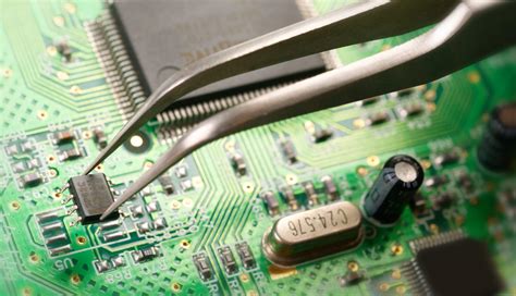
Problem 2: Poor Solder Joints
Poor solder joints can cause intermittent connections, increased resistance, and even complete failure of the LED PCB. This can be due to insufficient solder, excessive solder, or improper soldering techniques.
Solution:
- Use the appropriate amount of solder for each joint. Too little solder can result in a weak connection, while too much solder can cause bridging between adjacent pads.
- Ensure that the soldering iron temperature is set correctly for the type of solder being used.
- Use flux to improve solder flow and create a stronger bond between the component and the PCB.
- Implement a quality control process to inspect solder joints for consistency and integrity.

Problem 3: Overheating of LEDs
LEDs are sensitive to heat, and excessive temperatures can cause permanent damage, reduced light output, and shortened lifespan. Overheating can occur due to improper thermal management or incorrect current limiting.
Solution:
- Use a current-limiting resistor or a constant-current LED driver to regulate the current flowing through the LEDs.
- Incorporate adequate heat sinking measures, such as metal-core PCBs (MCPCBs), thermal vias, or external heatsinks, to dissipate heat effectively.
- Ensure proper ventilation and air flow around the LED PCB to prevent heat buildup.
- Monitor the LED temperature during operation and implement a thermal shutdown circuit if necessary.

Problem 4: Incorrect Current Limiting
Incorrect current limiting can lead to either insufficient light output or overdriving of the LEDs, resulting in reduced efficiency and potential damage.
Solution:
- Calculate the appropriate current-limiting resistor value based on the LED’s forward voltage and the desired current.
- Use a constant-current LED driver IC to precisely control the current through the LEDs, regardless of variations in supply voltage or LED forward voltage.
- Implement a current monitoring circuit to detect and prevent overcurrent conditions.
Problem 5: Electromagnetic Interference (EMI)
LED PCBs can generate electromagnetic interference (EMI) due to the fast switching nature of LEDs and their drivers. This can cause issues with nearby electronic devices and may violate electromagnetic compatibility (EMC) regulations.
Solution:
- Use proper PCB layout techniques, such as minimizing loop areas, using ground planes, and separating high-frequency traces from sensitive circuits.
- Implement EMI filtering components, such as ferrite beads, capacitors, and inductors, to suppress high-frequency noise.
- Use shielded cables and connectors for external connections to minimize EMI radiation.
- Conduct EMC testing to ensure compliance with relevant standards and regulations.
Problem 6: Inconsistent Light Output
Inconsistent light output across multiple LEDs on the same PCB can be caused by variations in LED binning, incorrect current balancing, or uneven thermal distribution.
Solution:
- Use LEDs from the same bin or with closely matched forward voltages to ensure consistent light output.
- Implement a current mirror circuit or a series-parallel LED configuration to balance the current across multiple LEDs.
- Ensure even thermal distribution across the PCB by using proper heat sinking and thermal management techniques.
- Consider using a light diffuser or mixing chamber to even out any remaining inconsistencies in light output.
Problem 7: Mechanical Stress and Vibration
LED PCBs used in harsh environments, such as automotive or industrial applications, may be subjected to mechanical stress and vibration. This can cause solder joint failures, component detachment, or even PCB fractures.
Solution:
- Use strain relief measures, such as flexible PCBs, underfill materials, or conformal coatings, to absorb and distribute mechanical stress.
- Implement robust PCB mounting methods, such as using vibration-dampening fasteners or shock-absorbing materials.
- Conduct vibration and shock testing to ensure the LED PCB can withstand the expected mechanical stresses in its intended application.
- Consider using surface-mount LEDs (SMD LEDs) instead of through-hole LEDs for better mechanical stability.
Frequently Asked Questions (FAQ)
1. What are the most common causes of LED failure on a PCB?
The most common causes of LED failure on a PCB include incorrect polarity, overheating, electrical overstress (EOS), and electrostatic discharge (ESD) damage.
2. How can I prevent solder bridging when hand-soldering LEDs?
To prevent solder bridging, use a fine-tipped soldering iron, apply an appropriate amount of solder, and ensure that the soldering iron temperature is set correctly. Additionally, using a magnifying lens or microscope can help you better control the soldering process.
3. What is the purpose of a current-limiting resistor in an LED circuit?
A current-limiting resistor is used to regulate the current flowing through an LED, preventing it from drawing excessive current that could cause damage or reduced lifespan. The resistor value is calculated based on the LED’s forward voltage and the desired current.
4. How can I improve the thermal management of my LED PCB?
To improve thermal management, consider using metal-core PCBs (MCPCBs), incorporating thermal vias, or attaching external heatsinks. Ensure proper ventilation and air flow around the PCB, and monitor the LED temperature during operation.
5. What should I do if I encounter inconsistent light output across multiple LEDs on the same PCB?
If you encounter inconsistent light output, first check if the LEDs are from the same bin or have closely matched forward voltages. Implement a current mirror circuit or a series-parallel LED configuration to balance the current across multiple LEDs. Additionally, ensure even thermal distribution across the PCB and consider using a light diffuser or mixing chamber to even out any remaining inconsistencies.
Conclusion
Troubleshooting LED PCB assembly problems requires a systematic approach and a thorough understanding of the underlying causes. By addressing issues such as incorrect LED polarity, poor solder joints, overheating, incorrect current limiting, EMI, inconsistent light output, and mechanical stress, you can ensure the optimal performance and reliability of your LED PCB.
Implementing appropriate solutions, such as proper PCB design, thermal management, current control, and mechanical protection, can help you overcome these challenges and create high-quality LED PCB assemblies. Additionally, conducting thorough testing and quality control processes can help identify and rectify any issues early in the production cycle, saving time and resources in the long run.
By following the guidelines and solutions outlined in this article, you can troubleshoot and resolve common LED PCB assembly problems effectively, ensuring the success of your LED-based projects.
| Problem | Solution |
|---|---|
| Incorrect LED Polarity | Double-check polarity, ensure clear PCB markings, use a multimeter, implement visual inspection |
| Poor Solder Joints | Use appropriate solder amount, set correct soldering iron temperature, use flux, implement quality control |
| Overheating of LEDs | Use current-limiting resistor or constant-current driver, incorporate heat sinking, ensure ventilation, monitor temperature |
| Incorrect Current Limiting | Calculate appropriate resistor value, use constant-current LED driver IC, implement current monitoring |
| Electromagnetic Interference (EMI) | Use proper PCB layout techniques, implement EMI filtering components, use shielded cables and connectors, conduct EMC testing |
| Inconsistent Light Output | Use LEDs from the same bin, implement current balancing, ensure even thermal distribution, consider light diffuser or mixing chamber |
| Mechanical Stress and Vibration | Use strain relief measures, implement robust PCB mounting methods, conduct vibration and shock testing, consider surface-mount LEDs |
No responses yet