Introduction to the 555 Timer IC
The 555 timer is one of the most popular and versatile integrated circuits (ICs) used in electronic projects. This small 8-pin chip can be configured to create a variety of timing and pulse generation applications, including delays, oscillators, and pulse width modulation (PWM) control. Its simplicity, reliability, and low cost make it an essential component for hobbyists, students, and professionals alike.
In this article, we will focus on using the 555 timer to create a delay circuit. We’ll explore the components required, how to design and build the circuit, and discuss some practical applications for this type of timer.
Understanding the 555 Timer Pinout and Functions
Before diving into the delay circuit, let’s familiarize ourselves with the 555 timer’s pinout and the function of each pin.
| Pin Number | Pin Name | Description |
|---|---|---|
| 1 | GND | Ground |
| 2 | TRIGGER | Negative pulse input to start timing |
| 3 | OUTPUT | Output pin (HIGH or LOW) |
| 4 | RESET | Active-low reset input |
| 5 | CONTROL | Control voltage input |
| 6 | THRESHOLD | Input to set the upper threshold voltage |
| 7 | DISCHARGE | Open collector output to discharge the timing capacitor |
| 8 | VCC | Positive supply voltage (4.5V to 16V) |
The 555 timer has two main operational modes: monostable (one-shot) and astable (oscillator). In monostable mode, which we’ll use for our delay circuit, the timer produces a single output pulse of a specified duration when triggered.
Designing a 555 Timer Delay Circuit
To create a 555 timer delay circuit, we need to understand the basic design principles and calculate the appropriate component values.
Circuit Diagram
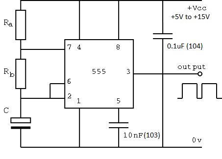
Here’s a simple 555 timer delay circuit diagram:
           +--------+
      VCC -|8      4|- RESET
           |        |
           |7      3|- OUTPUT
           |        |
TRIGGER -|2  555  6|- THRESHOLD
           |        |
        ---|1      5|- CONTROL
        |  +--------+  |
      -----            |
       ---             |
        -              |
       GND             |
                       |
                      ___
                     /   \
                     \___/  TIMING CAPACITOR
                       |
                      ___
                     /   \
                     \___/  TIMING RESISTOR
                       |
                      GND
Component Selection
To build the 555 timer delay circuit, you’ll need the following components:
- 555 timer IC
- Timing resistor (R)
- Timing capacitor (C)
- Decoupling capacitor (0.01µF to 0.1µF ceramic)
- LED and current-limiting resistor (optional, for output indication)
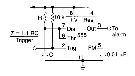
The timing resistor and capacitor values determine the delay duration. Use the following formula to calculate the delay time:
Delay Time (seconds) = 1.1 × R (ohms) × C (farads)
For example, if you want a 5-second delay using a 100µF capacitor, you can calculate the required resistor value:
R = Delay Time / (1.1 × C)
  = 5 / (1.1 × 100 × 10⁻⁶)
  ≈ 45kΩ
Step-by-Step Assembly Instructions
- Connect pin 1 (GND) of the 555 timer to ground.
- Connect pin 8 (VCC) to the positive supply voltage (4.5V to 16V).
- Connect the decoupling capacitor between VCC and GND.
- Connect the timing resistor between pins 7 (DISCHARGE) and 8 (VCC).
- Connect the timing capacitor between pins 6 (THRESHOLD) and 1 (GND).
- Connect pin 2 (TRIGGER) to GND through a momentary switch or a trigger signal source.
- (Optional) Connect an LED and current-limiting resistor between pin 3 (OUTPUT) and GND for output indication.

Testing and Troubleshooting Your 555 Timer Delay Circuit
After assembling your 555 timer delay circuit, it’s essential to test its functionality and troubleshoot any issues that may arise.
Testing Procedure
- Double-check all connections to ensure they are correct and secure.
- Apply power to the circuit.
- Trigger the delay by momentarily connecting pin 2 (TRIGGER) to GND.
- Observe the output LED (if used) or measure the voltage at pin 3 (OUTPUT) using a multimeter or oscilloscope.
- Verify that the delay duration matches your calculated value.
Common Issues and Solutions
- No output pulse:
- Check the power supply and ensure the 555 timer is receiving the correct voltage.
- Verify that the trigger signal is properly connected and activating the timer.
-
Ensure the timing resistor and capacitor are correctly connected and have the appropriate values.
-
Incorrect delay duration:
- Recalculate the timing resistor and capacitor values and ensure they match your desired delay.
-
Check for any leakage or damaged components that may affect the timing.
-
Unstable or inconsistent output:
- Ensure the decoupling capacitor is connected correctly between VCC and GND.
- Keep the wiring short and neat to minimize noise and interference.
- Use a stable power supply with sufficient current capacity.
Applications of 555 Timer Delay Circuits
555 timer delay circuits find applications in various fields, from home automation to industrial control systems. Some examples include:
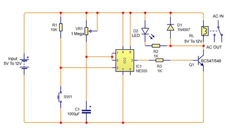
- Delayed relay activation
- Sequential lighting control
- Timed irrigation systems
- Delayed alarm triggering
- Timed motor control
- Time-lapse photography triggers
- Delayed power-on circuits for audio amplifiers
Modifying and Enhancing Your 555 Timer Delay Circuit
Once you’ve mastered the basic 555 timer delay circuit, you can explore various modifications and enhancements to suit your specific needs.
Adjustable Delay Duration
To make the delay duration adjustable, replace the fixed timing resistor with a potentiometer. By adjusting the potentiometer’s resistance, you can change the delay time within a specific range.
Cascaded Delays
You can create a sequence of delays by cascading multiple 555 timer delay circuits. Connect the output of one stage to the trigger input of the next stage, and so on.
Retriggerable Delay
To make the delay circuit retriggerable, connect a diode between the trigger input and the output. This allows the delay to be restarted if a new trigger signal is received during the delay period.
Combining with Other Circuits
Integrate your 555 timer delay circuit with other circuits, such as logic gates, comparators, or sensors, to create more advanced and interactive projects.
Conclusion
The 555 timer delay circuit is a simple yet powerful tool for introducing precise timing control in your electronic projects. By understanding the basics of the 555 timer IC, designing your circuit, and exploring various applications and modifications, you can unlock a world of possibilities in DIY electronics.
As you continue to work with 555 timer circuits, remember to experiment, learn from your mistakes, and share your knowledge with others in the community. Happy tinkering!
FAQ
Q1: What is the minimum and maximum delay time I can achieve with a 555 timer delay circuit?
A1: The minimum and maximum delay times depend on the timing resistor and capacitor values you choose. Practically, the minimum delay is limited by the 555 timer’s internal response time (around 10µs), while the maximum delay is limited by the leakage current of the capacitor and the maximum resistance value (around 10 minutes with a 100µF capacitor and 10MΩ resistor).
Q2: Can I use a 555 timer delay circuit with a microcontroller?
A2: Yes, you can use a 555 timer delay circuit in conjunction with a microcontroller. The microcontroller can trigger the delay circuit or read the output state of the timer. This can be useful in applications where the microcontroller needs to offload timing tasks or when precise delays are required.
Q3: How accurate is the delay time in a 555 timer delay circuit?
A3: The accuracy of the delay time depends on several factors, including the tolerance of the timing resistor and capacitor, the stability of the power supply, and the temperature. Typically, you can expect an accuracy within 5-10% of the calculated delay time. For more precise timing, consider using a crystal-controlled oscillator or a microcontroller with a built-in timer.
Q4: Can I power my 555 timer delay circuit using batteries?
A4: Yes, you can power your 555 timer delay circuit using batteries. The 555 timer IC can operate with a supply voltage range of 4.5V to 16V. When using batteries, ensure that the total voltage is within this range and that the batteries can provide sufficient current for your circuit.
Q5: Are there any alternatives to the 555 timer IC for creating delay circuits?
A5: Yes, there are several alternatives to the 555 timer IC for creating delay circuits, such as:
- Microcontrollers with built-in timers
- Dedicated timer ICs (e.g., 556, 558, LM122)
- CMOS timer ICs (e.g., ICM7555, TLC555)
- Analog delay circuits using op-amps and capacitors
- Digital delay circuits using shift registers or counters
Each alternative has its own advantages and disadvantages, such as cost, complexity, and precision. Choose the best option based on your specific requirements and available resources.
No responses yet