Introduction to the 555 Pulse Generator
The 555 pulse generator, also known as the 555 timer IC, is one of the most widely used and versatile integrated circuits in electronics. Developed by Signetics in 1971, the 555 timer has found its way into countless applications, from simple timing circuits to complex control systems. Its popularity stems from its ease of use, low cost, and reliability.
What is a Pulse Generator?
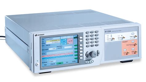
A pulse generator is an electronic device that produces a series of electrical pulses at regular intervals. These pulses can be used to control other devices, trigger events, or provide timing signals. Pulse generators are used in a wide range of applications, including:
- Timers and alarms
- Oscillators and clock circuits
- Pulse width modulation (PWM) control
- Frequency generation
- Sequencing and timing control
How the 555 Timer Works
The 555 timer IC consists of several functional blocks that work together to generate pulses:
- Voltage divider: A resistive voltage divider network sets the threshold and trigger levels.
- Comparators: Two comparators monitor the voltage levels and control the flip-flop.
- Flip-flop: A bistable flip-flop is used to store the output state.
- Discharge transistor: A transistor is used to discharge the timing capacitor.
- Output stage: A push-pull output stage provides high current drive capability.
555 Timer Pinout
The 555 timer IC comes in an 8-pin DIP package with the following pinout:
| Pin | Name | Function |
|---|---|---|
| 1 | GND | Ground |
| 2 | TRIGGER | Negative pulse input to trigger the timer |
| 3 | OUTPUT | Output pin, can source or sink current |
| 4 | RESET | Active-low reset input |
| 5 | CONTROL | Control voltage input for setting threshold levels |
| 6 | THRESHOLD | Input to set the upper threshold voltage |
| 7 | DISCHARGE | Open-collector output to discharge timing capacitor |
| 8 | VCC | Positive supply voltage (4.5V to 16V) |
Basic 555 Timer Modes
The 555 timer can be configured to operate in two basic modes:
-
Monostable mode (one-shot): In this mode, the 555 timer generates a single pulse of a predetermined duration when triggered. The pulse duration is set by an external RC network.
-
Astable mode (oscillator): In this mode, the 555 timer generates a continuous stream of pulses at a frequency determined by an external RC network. The duty cycle of the output pulses can also be adjusted.

555 Timer Monostable Mode
In monostable mode, the 555 timer generates a single output pulse of a specific duration when triggered by an input pulse. The duration of the output pulse is determined by an external resistor (R) and capacitor (C) connected to the timer.
Monostable Mode Circuit
A basic 555 timer monostable circuit consists of the following components:
- 555 timer IC
- Timing resistor (R)
- Timing capacitor (C)
- Trigger switch or input
The timing resistor is connected between the VCC and DISCHARGE pins, while the timing capacitor is connected between the THRESHOLD and GND pins. The trigger input is connected to the TRIGGER pin, usually through a switch or a signal source.
Calculating Pulse Duration
The duration of the output pulse in monostable mode is determined by the values of the timing resistor (R) and capacitor (C) according to the following formula:
t = 1.1 × R × C
Where:
– t is the pulse duration in seconds
– R is the timing resistor value in ohms
– C is the timing capacitor value in farads
For example, if R = 100 kΩ and C = 10 µF, the pulse duration would be:
t = 1.1 × 100,000 × 0.00001 = 1.1 seconds
Monostable Mode Applications
Some common applications of the 555 timer in monostable mode include:
- Debouncing switches
- Generating time delays
- One-shot pulse generation
- Triggering events or alarms
- Pulse stretching or shaping

555 Timer Astable Mode
In astable mode, the 555 timer generates a continuous stream of pulses at a frequency determined by an external resistor-capacitor (RC) network. The duty cycle of the output pulses can also be adjusted by varying the values of the resistors in the RC network.
Astable Mode Circuit
A basic 555 timer astable circuit consists of the following components:
- 555 timer IC
- Timing resistors (R1 and R2)
- Timing capacitor (C)
The timing resistors R1 and R2 are connected in series between the VCC and DISCHARGE pins, with the junction between them connected to the THRESHOLD pin. The timing capacitor is connected between the TRIGGER pin and GND.
Calculating Frequency and Duty Cycle
The frequency and duty cycle of the output pulses in astable mode are determined by the values of the timing resistors (R1 and R2) and capacitor (C) according to the following formulas:
Frequency (f) = 1.44 / ((R1 + 2 × R2) × C)
Duty Cycle (D) = (R1 + R2) / (R1 + 2 × R2)
Where:
– f is the output frequency in hertz
– R1 and R2 are the timing resistor values in ohms
– C is the timing capacitor value in farads
– D is the duty cycle expressed as a fraction
For example, if R1 = 1 kΩ, R2 = 10 kΩ, and C = 0.1 µF, the output frequency and duty cycle would be:
f = 1.44 / ((1,000 + 2 × 10,000) × 0.0000001) ≈ 690 Hz
D = (1,000 + 10,000) / (1,000 + 2 × 10,000) ≈ 0.52 or 52%
Astable Mode Applications
Some common applications of the 555 timer in astable mode include:
- Generating clock signals
- Pulse width modulation (PWM) control
- Morse code generators
- LED and lamp flashers
- Tone generators and sirens

Advanced 555 Timer Techniques
While the basic monostable and astable modes cover a wide range of applications, the 555 timer can also be used in more advanced configurations to achieve specific functions or improve performance.
Cascading 555 Timers
Multiple 555 timers can be cascaded together to create more complex timing sequences or to generate longer time delays. In a cascaded configuration, the output of one 555 timer triggers the next, allowing for sequential or interdependent timing events.
Voltage Controlled Oscillator (VCO)
By replacing the timing resistor with a potentiometer or a voltage-controlled resistor (such as a JFET), the output frequency of the 555 timer can be made to vary with an input control voltage. This configuration is known as a voltage-controlled oscillator (VCO) and is useful in applications such as:
- Frequency modulation (FM) synthesis
- Voltage-to-frequency conversion
- Sweep generators
- Phase-locked loops (PLLs)
Pulse Width Modulation (PWM)
Pulse width modulation is a technique used to control the power delivered to a load by varying the duty cycle of a pulsed signal. The 555 timer can be configured as a PWM controller by adjusting the timing resistors to vary the duty cycle in response to an input control signal. PWM is commonly used in:
- DC motor speed control
- LED dimming
- Power supply regulation
- Temperature control systems
Schmidt Trigger and Hysteresis
The 555 timer’s internal comparators have built-in hysteresis, which helps to prevent false triggering due to noise or slow-moving input signals. This property can be exploited to create a Schmidt trigger, which provides a clean, snap-action response to slowly changing inputs. Schmidt triggers are useful for:
- Debouncing mechanical switches
- Conditioning noisy signals
- Generating clean edges from slow-moving waveforms
Troubleshooting and Best Practices
When working with 555 timers, there are several best practices and troubleshooting tips to keep in mind:
-
Decoupling capacitors: Always use a decoupling capacitor (0.01 µF to 0.1 µF) between the VCC and GND pins to prevent supply noise and ensure stable operation.
-
Timing capacitor selection: Use high-quality, low-leakage capacitors for the timing capacitor to ensure accurate and stable timing. Avoid electrolytic capacitors, as they can introduce errors due to their high leakage and temperature sensitivity.
-
Timing resistor range: Keep the timing resistor values within the recommended range (1 kΩ to 1 MΩ) to ensure proper operation and avoid excessive current draw.
-
Reset function: Use the reset pin to ensure a known starting state for the timer, especially in monostable mode. Tie the reset pin to VCC if not used.
-
Output loading: Be mindful of the output current limitations of the 555 timer. The output can typically sink or source up to 200 mA, but check the datasheet for your specific device.
-
Interference and noise: Keep the 555 timer circuit away from sources of electromagnetic interference (EMI) and use proper grounding and shielding techniques to minimize noise pickup.
-
Simulation and prototyping: Always simulate your 555 timer circuit using a software tool like SPICE before building the physical prototype. This can help identify potential issues and optimize the design.
FAQ
- What is the maximum supply voltage for a 555 timer?
-
The maximum supply voltage for a standard 555 timer is 16V. However, some low-voltage versions can operate down to 2V.
-
Can a 555 timer be used to generate a 50% duty cycle square wave?
-
Yes, in astable mode, a 50% duty cycle can be achieved by making R1 much smaller than R2 (e.g., R1 = 1 kΩ, R2 = 100 kΩ).
-
How accurate is the timing of a 555 timer?
-
The timing accuracy of a 555 timer depends on several factors, including the accuracy of the external components (resistors and capacitors), supply voltage stability, and temperature. Typical timing accuracy is around 1-5%, but this can be improved with careful component selection and circuit design.
-
Can a 555 timer be used as a voltage comparator?
-
Yes, the 555 timer’s internal comparators can be used as a standalone voltage comparator by connecting the threshold and trigger inputs to the voltages to be compared and using the output to indicate the comparison result.
-
What is the minimum pulse width that a 555 timer can generate in monostable mode?
- The minimum pulse width is determined by the propagation delay of the 555 timer, which is typically around 10-100 ns. In practice, pulse widths of a few microseconds or greater are more common due to the limitations of the external timing components.
Conclusion
The 555 pulse generator is a versatile and widely used integrated circuit that finds applications in a broad range of electronic systems. By understanding its basic operating principles, modes of operation, and advanced techniques, designers can harness the power of the 555 timer to create reliable and efficient timing and control circuits. Whether used as a simple timer, an oscillator, or a pulse width modulator, the 555 timer remains an essential tool in the electronics engineer’s toolkit.

No responses yet