Introduction to the 2N5088 Transistor
The 2N5088 is a popular NPN bipolar junction transistor (BJT) that is widely used in electronic circuits for amplification and switching applications. This transistor is known for its high current gain, low saturation voltage, and fast switching speed, making it suitable for a wide range of projects.
Key Specifications of the 2N5088
| Parameter | Value |
|---|---|
| Collector-Emitter Voltage | 30V |
| Collector-Base Voltage | 60V |
| Emitter-Base Voltage | 6V |
| Collector Current | 100mA |
| Power Dissipation | 625mW |
| Current Gain (hFE) | 100-300 |
| Transition Frequency (fT) | 50MHz |
The 2N5088’s key specifications make it well-suited for low-power, high-frequency applications. Its high current gain allows for efficient amplification, while its fast switching speed enables its use in digital circuits.
Understanding the Pinout and Package
2N5088 Pinout
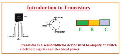
The 2N5088 transistor has three pins: the collector (C), base (B), and emitter (E). The pinout is as follows:
| Pin | Function |
|---|---|
| 1 | Emitter |
| 2 | Base |
| 3 | Collector |
It’s crucial to identify the correct pinout when using the 2N5088 in your projects to ensure proper functionality and avoid damaging the transistor or other components.
TO-92 Package
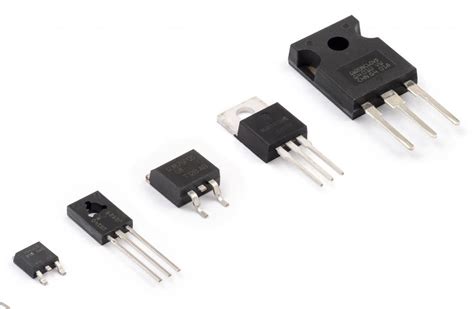
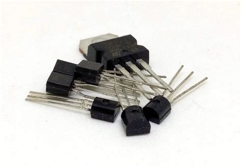
The 2N5088 comes in a TO-92 package, which is a small, plastic-encapsulated package commonly used for transistors. The TO-92 package has a cylindrical shape with a flat side that indicates the emitter pin.

Biasing the 2N5088 Transistor
Proper biasing is essential for the 2N5088 to function correctly in your circuit. There are two main biasing configurations: common-emitter and common-collector.
Common-Emitter Configuration
In the common-emitter configuration, the emitter is connected to ground, and the input signal is applied to the base. The amplified output signal is taken from the collector. This configuration provides high voltage and current gain, making it suitable for amplification applications.
To bias the 2N5088 in a common-emitter configuration, follow these steps:
1. Connect the emitter to ground.
2. Apply a voltage divider to the base to set the quiescent point.
3. Connect a load resistance to the collector.
4. Provide a collector supply voltage through the load resistance.
Common-Collector Configuration (Emitter Follower)
The common-collector configuration, also known as an emitter follower, has the collector connected to the positive supply voltage, and the output signal is taken from the emitter. This configuration provides high current gain and low output impedance, making it useful for Impedance Matching and buffering applications.
To bias the 2N5088 in a common-collector configuration:
1. Connect the collector to the positive supply voltage.
2. Apply the input signal to the base.
3. Connect the emitter to the load resistance.
4. Provide a base bias voltage using a voltage divider.

Amplifier Circuits Using the 2N5088
The 2N5088 transistor is commonly used in various amplifier circuits, such as audio amplifiers, pre-amplifiers, and small-Signal amplifiers.
Simple Audio Amplifier
A simple audio amplifier using the 2N5088 can be built using the following components:
- 2N5088 transistor
- 10kΩ potentiometer for volume control
- 100kΩ resistor for base bias
- 1kΩ resistor for emitter bias
- 10μF coupling capacitors
- 8Ω speaker
To construct the audio amplifier:
1. Connect the potentiometer as a voltage divider to provide base bias.
2. Use the coupling capacitors to connect the input signal to the potentiometer and the transistor’s base to the emitter bias resistor.
3. Connect the speaker between the transistor’s collector and the positive supply voltage.
This simple audio amplifier provides moderate gain and can drive small speakers for hobbyist projects.
Small-Signal Amplifier
A small-signal amplifier using the 2N5088 is useful for amplifying weak signals from sensors or other low-level sources. To build a small-signal amplifier:
- Bias the 2N5088 in a common-emitter configuration.
- Use a 1kΩ collector load resistance.
- Choose base bias resistors to set the quiescent point at about half the supply voltage.
- Couple the input signal to the base using a capacitor.
- Take the amplified output signal from the collector through another coupling capacitor.
This small-signal amplifier provides high gain and can be cascaded with additional stages for even greater amplification.

Switching Applications with the 2N5088
The 2N5088’s fast switching speed and high current gain make it suitable for various switching applications, such as digital logic circuits and relay drivers.
Simple Transistor Switch
A simple transistor switch using the 2N5088 can be used to control loads, such as LEDs or small relays, from digital inputs. To create a transistor switch:
- Connect the load between the collector and the positive supply voltage.
- Connect a base resistor between the input signal and the base.
- Apply a voltage to the base that exceeds the transistor’s VBE (about 0.7V) to turn the switch on.
When the input signal is high, the transistor will conduct, allowing current to flow through the load. When the input is low, the transistor will be off, and no current will flow.
Relay Driver
The 2N5088 can also be used as a relay driver to control larger loads. To build a relay driver:
- Connect the relay coil between the collector and the positive supply voltage.
- Use a flyback diode across the relay coil to protect the transistor from voltage spikes.
- Connect a base resistor between the input signal and the base.
- Ensure the transistor can handle the relay coil’s current draw.
When the input signal is high, the transistor will conduct, energizing the relay coil and switching the relay contacts. When the input is low, the transistor will be off, and the relay will be de-energized.
Choosing the Right Resistor Values
Selecting the appropriate resistor values is crucial for ensuring the 2N5088 operates within its specified limits and provides the desired performance in your circuit.
Base Resistor Selection
The base resistor value determines the base current and, consequently, the collector current. To calculate the base resistor value:
- Determine the desired collector current based on the load requirements.
- Calculate the base current using the transistor’s current gain (hFE).
- Use Ohm’s law to determine the base resistor value based on the input voltage and required base current.
For example, if you need a collector current of 10mA and the transistor has an hFE of 200, the base current would be 10mA / 200 = 50μA. If the input voltage is 5V, the base resistor value would be (5V – 0.7V) / 50μA = 86kΩ.
Collector Load Resistor Selection
The collector load resistor value affects the voltage gain and output swing of the amplifier. To choose the collector load resistor:
- Determine the desired voltage gain.
- Consider the transistor’s maximum collector current and power dissipation ratings.
- Use Ohm’s law to calculate the collector load resistor value based on the desired voltage drop and collector current.
For example, if you want a voltage gain of 10 and the collector current is 1mA, the collector load resistor value would be 10 * (VCC – VCE) / 1mA, where VCC is the supply voltage and VCE is the transistor’s collector-emitter voltage.
Troubleshooting Tips
If your 2N5088 circuit is not working as expected, consider the following troubleshooting tips:
- Double-check the transistor’s pinout and ensure it is connected correctly.
- Verify that the base-emitter junction is properly forward-biased.
- Ensure the collector load resistor is not too large, which could limit the collector current.
- Check the transistor’s power dissipation and make sure it is not exceeding its maximum rating.
- Use a multimeter to measure voltages and currents at various points in the circuit to isolate the problem.
FAQ
1. What is the maximum collector-emitter voltage for the 2N5088?
The maximum collector-emitter voltage for the 2N5088 is 30V. Exceeding this voltage can damage the transistor.
2. Can I use the 2N5088 for high-power applications?
The 2N5088 is designed for low-power applications, with a maximum power dissipation of 625mW. For high-power applications, consider using power transistors with higher current and power ratings.
3. Is the 2N5088 suitable for high-frequency applications?
The 2N5088 has a transition frequency (fT) of 50MHz, making it suitable for low to medium-frequency applications. For high-frequency applications, consider using transistors with higher fT values.
4. Can I replace the 2N5088 with another transistor?
If you need to replace the 2N5088 in your circuit, look for transistors with similar specifications, such as the BC547 or 2N3904. Always verify that the replacement transistor meets your circuit’s requirements.
5. How do I test a 2N5088 transistor?
To test a 2N5088 transistor, use a multimeter to perform a continuity test between the pins. A functional transistor should show continuity between the collector and emitter when the base-emitter junction is forward-biased, and no continuity when it is not. Also, check for shorts between the pins, which would indicate a damaged transistor.
Conclusion
The 2N5088 transistor is a versatile component that finds applications in amplification, switching, and signal conditioning circuits. By understanding its pinout, biasing requirements, and typical use cases, you can effectively incorporate the 2N5088 into your projects.
When designing circuits with the 2N5088, pay close attention to the resistor values, ensure proper biasing, and consider the transistor’s limitations. By following the guidelines and examples provided in this article, you can successfully use the 2N5088 transistor in your electronic projects.

No responses yet