Introduction to the 1N4002 Diode
The 1N4002 diode is a popular rectifier diode widely used in various electronic applications. It is part of the 1N400x series of diodes, which are known for their reliability, affordability, and versatility. In this comprehensive guide, we will explore the characteristics, applications, and important considerations when using the 1N4002 diode.
What is a Diode?
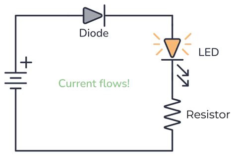
Before diving into the specifics of the 1N4002 diode, let’s briefly discuss what a diode is. A diode is a two-terminal electronic component that allows current to flow in only one direction, from the anode to the cathode. It acts as a one-way valve for electrical current, blocking current flow in the reverse direction.
Diodes are made from semiconductor materials, typically silicon or germanium, and are used in various applications such as rectification, voltage regulation, signal conditioning, and overvoltage protection.

Characteristics of the 1N4002 Diode
Maximum Ratings
The 1N4002 diode has specific maximum ratings that should not be exceeded to ensure proper operation and prevent damage to the component. Here are the key maximum ratings:
| Parameter | Value |
|---|---|
| Peak Repetitive Reverse Voltage (VRRM) | 100 V |
| Average Rectified Forward Current (IO) | 1 A |
| Non-Repetitive Peak Forward Surge Current (IFSM) | 30 A |
| Maximum Instantaneous Forward Voltage Drop (VF) | 1.1 V |
| Operating Junction Temperature Range (TJ) | -65°C to +175°C |
It is crucial to adhere to these maximum ratings when designing circuits and selecting the appropriate diode for your application.
Forward Voltage Drop
The forward voltage drop (VF) is the voltage across the diode when it is conducting current in the forward direction. For the 1N4002 diode, the typical forward voltage drop is approximately 0.7 V to 1.1 V, depending on the forward current.
It is important to consider the forward voltage drop when designing circuits, as it can impact the overall voltage regulation and power dissipation of the system.
Reverse Recovery Time
The reverse recovery time (trr) is the time required for the diode to switch from the conducting state to the blocking state when the polarity of the applied voltage reverses. For the 1N4002 diode, the typical reverse recovery time is around 2 μs.
A shorter reverse recovery time is desirable in applications where fast switching is required, such as in high-frequency rectification or switching power supplies.

Applications of the 1N4002 Diode
The 1N4002 diode finds use in a wide range of electronic applications. Let’s explore some common applications:
Rectification
One of the primary applications of the 1N4002 diode is in rectifier circuits. Rectification is the process of converting alternating current (AC) to direct current (DC). The 1N4002 diode is commonly used in half-wave and full-wave rectifier circuits to convert AC voltage to pulsating DC voltage.
Voltage Clamping
The 1N4002 diode can be used in voltage Clamping Circuits to limit the peak voltage across a load or to protect sensitive components from overvoltage conditions. By placing the diode in parallel with the load, it conducts when the voltage exceeds a certain threshold, effectively clamping the voltage to a safe level.
Reverse Polarity Protection
In some applications, it is essential to protect circuits from accidental reverse polarity connections. The 1N4002 diode can be used as a reverse polarity protection device by placing it in series with the power supply. If the polarity is reversed, the diode will block the current flow, preventing damage to the circuit.
Flyback Diodes
In inductive load circuits, such as relay coils or motors, the 1N4002 diode can be used as a flyback diode. When the current through an inductive load is suddenly interrupted, a high-voltage spike can occur due to the collapsing magnetic field. The flyback diode provides a path for the induced current, protecting the switching device and reducing voltage spikes.

Selecting the Right Diode
When selecting a diode for your application, it is important to consider several factors to ensure optimal performance and reliability. Here are some key considerations:
Voltage and Current Ratings
Choose a diode with voltage and current ratings that exceed the maximum values expected in your circuit. The peak repetitive reverse voltage (VRRM) should be higher than the maximum reverse voltage the diode will encounter, and the average rectified forward current (IO) should be sufficient for your current requirements.
Package and Mounting
Diodes are available in various package types, such as through-hole, surface mount, and axial lead packages. Consider the physical dimensions, mounting requirements, and thermal characteristics of the diode package to ensure compatibility with your circuit board and assembly process.
Temperature Range
Ensure that the operating temperature range of the diode is suitable for your application. The 1N4002 diode has a wide operating junction temperature range of -65°C to +175°C, making it suitable for most general-purpose applications.
Reverse Recovery Time
If your application requires fast switching or operates at high frequencies, consider diodes with shorter reverse recovery times. The 1N4002 diode has a typical reverse recovery time of 2 μs, which is suitable for many applications but may not be optimal for high-speed switching.
Frequently Asked Questions (FAQ)
1. Can I use a 1N4002 diode for high-frequency applications?
While the 1N4002 diode can be used in many general-purpose applications, it may not be the best choice for high-frequency applications due to its relatively long reverse recovery time. For high-frequency applications, consider using diodes specifically designed for fast switching, such as Schottky diodes or ultrafast recovery diodes.
2. What is the difference between a 1N4002 diode and a 1N4007 diode?
The main difference between the 1N4002 and 1N4007 diodes is their maximum peak repetitive reverse voltage (VRRM) rating. The 1N4002 has a VRRM of 100 V, while the 1N4007 has a higher VRRM of 1000 V. The choice between the two depends on the specific voltage requirements of your application.
3. Can I use a 1N4002 diode for voltage regulation?
While the 1N4002 diode can be used in simple voltage regulation circuits, such as in a zener diode voltage regulator, it is not designed specifically for voltage regulation purposes. For more precise and efficient voltage regulation, consider using dedicated voltage regulator ICs or specialized diodes like zener diodes.
4. How do I determine the power dissipation of a 1N4002 diode in my circuit?
To determine the power dissipation of a 1N4002 diode, you need to calculate the product of the forward voltage drop (VF) and the average forward current (IF) through the diode. The power dissipation (PD) can be expressed as: PD = VF × IF. Ensure that the calculated power dissipation does not exceed the maximum rated value specified in the diode’s datasheet.
5. Can I replace a 1N4002 diode with a different diode in my circuit?
When replacing a 1N4002 diode with a different diode, it is important to consider the specifications and ratings of both diodes. The replacement diode should have equal or better voltage and current ratings, similar forward voltage drop, and comparable reverse recovery time. It is always recommended to refer to the datasheets of both diodes to ensure compatibility and proper operation in your specific application.
Conclusion
The 1N4002 diode is a versatile and widely used rectifier diode that finds applications in various electronic circuits. Understanding its characteristics, maximum ratings, and common applications is crucial for selecting the right diode for your project.
When designing circuits with the 1N4002 diode, consider factors such as voltage and current ratings, package and mounting requirements, temperature range, and reverse recovery time. By carefully evaluating these factors and following the guidelines provided in this article, you can effectively incorporate the 1N4002 diode into your electronic designs.
Remember to always refer to the diode’s datasheet for detailed specifications and consult with experienced professionals if you have any doubts or require further guidance.
Happy diode designing!
No responses yet