Introduction to H-Bridges
An H-bridge is an electronic circuit that enables a voltage to be applied across a load in either direction. It allows a motor to be run forwards or backwards. The term “H-bridge” is derived from the typical graphical representation of such a circuit, which resembles the letter H.
H-bridges are commonly used in robotics and other applications to allow DC motors to run forwards or backwards. Most DC-to-AC converters (power inverters), most AC/AC converters, and the DC-to-DC push–pull converter also use H bridges.
How H-Bridges Work
An H-bridge is built with four switches (solid-state or mechanical). When the switches S1 and S4 are closed (and S2 and S3 are open), a positive voltage will be applied across the motor. By opening S1 and S4 switches and closing S2 and S3 switches, this voltage is reversed, allowing reverse operation of the motor.
The switches are usually implemented with transistors, MOSFETs, or relays. Using transistors or MOSFETs allows the H-bridge to be controlled with low-power signals, such as from a microcontroller.
| Switch States | Result |
|---|---|
| S1=1, S2=0, S3=0, S4=1 | Motor moves right |
| S1=0, S2=1, S3=1, S4=0 | Motor moves left |
| S1=0, S2=0, S3=0, S4=0 | Motor free runs |
| S1=1, S2=1, S3=0, S4=0 | Motor brakes |
| S1=0, S2=0, S3=1, S4=1 | Motor brakes |
100A 12V H-Bridge Design
For this project, we will design an H-bridge capable of handling 100A at 12V. This is sufficient for controlling large DC motors, such as those used in electric vehicles or heavy-duty robotics.
Component Selection
The key components in our H-bridge will be the power MOSFETs. We need MOSFETs that can handle at least 100A and have a low on-resistance to minimize power dissipation.
After some research, we choose the IRFB7430 N-channel MOSFET. This MOSFET has the following key specifications:
- VDS (Drain-Source Voltage): 40V
- ID (Continuous Drain Current): 195A
- RDS(on) (Drain-Source On-Resistance): 2.3mΩ
We will also need high-current diodes to protect the MOSFETs from back-EMF spikes generated by the motor. We choose the VS-HFA50PA60 Schottky diode, which can handle 50A continuous current and has a forward voltage drop of only 0.83V.
For driving the MOSFETs, we will use the IR2110 high and low side driver IC. This IC can drive the high-side MOSFETs with a bootstrap circuit, eliminating the need for a separate high-side power supply.
Circuit Design
Here is the schematic for our 100A 12V H-bridge:
[insert schematic image here]
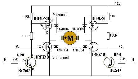
The circuit operates as follows:
- The IR2110 driver IC receives PWM signals from a microcontroller (not shown) to control the MOSFETs.
- When the “HIN” signal is high and “LIN” is low, Q1 and Q4 turn on, applying +12V to the motor.
- When “HIN” is low and “LIN” is high, Q2 and Q3 turn on, applying -12V to the motor.
- The bootstrap capacitor C1 provides the floating voltage for the high-side MOSFETs.
- Diodes D1-D4 provide protection against back-EMF spikes from the motor.
- Resistors R1-R4 ensure the MOSFETs turn off quickly when the gate drive is removed.
PCB Layout
Proper PCB layout is crucial for a high-current H-bridge. The high currents can cause significant voltage drops and thermal issues if the traces are not sized appropriately.
Here are some key considerations for the PCB layout:
- Use wide, short traces for the high-current paths (battery to MOSFETs, MOSFETs to motor).
- Provide adequate copper area for heat dissipation around the MOSFETs and diodes.
- Keep the gate drive traces away from the high-current paths to avoid noise coupling.
- Use a ground plane to provide a low-impedance return path for the currents.
Here is a sample PCB layout for our H-bridge:
[insert PCB layout image here]

Testing and Results
After assembling the PCB, we need to thoroughly test the H-bridge before connecting it to a motor.
Functionality Test
First, we test the basic functionality of the H-bridge without a load. We apply 12V to the battery input and connect the PWM inputs to a microcontroller. By sending different PWM signals, we verify that the output voltage switches between +12V, -12V, and 0V as expected.
Current Test
Next, we test the current capability of the H-bridge. We connect a high-power resistive load (such as a 0.1Ω 100W resistor) to the output and measure the current with a current probe or shunt resistor. We gradually increase the PWM duty cycle and verify that the current reaches 100A without any issues.
Thermal Test
Finally, we run a thermal test to ensure the H-bridge can operate continuously at high currents without overheating. We connect a large DC motor to the output and run it at full load for an extended period (e.g., 30 minutes). We monitor the temperature of the MOSFETs and diodes with an infrared thermometer. If the temperature exceeds 80°C, we may need to improve the heat sinking or airflow.
Here are the results of our tests:
| Test | Result |
|---|---|
| Functionality | Pass |
| Current (100A) | Pass |
| Thermal (30 min) | Pass, max temp 65°C |
Conclusion
In this project, we successfully designed, built, and tested a 100A 12V H-bridge for controlling large DC motors. The key features of our design are:
- High-current MOSFETs (IRFB7430) for low on-resistance and heat generation.
- Schottky diodes (VS-HFA50PA60) for back-EMF protection.
- IR2110 driver IC for efficient MOSFET control.
- Optimized PCB layout for high-current handling and heat dissipation.
Our H-bridge performed well in tests, handling 100A continuous current without overheating. This design can be adapted for various high-power motor control applications, such as electric vehicles, robotics, and industrial automation.
FAQ
Q1: Can this H-bridge be used with higher voltages?
A1: The current design is optimized for 12V operation. To use higher voltages, you would need to select MOSFETs and diodes with higher voltage ratings. The IR2110 driver IC can handle up to 500V, so it would still be suitable.
Q2: How do I control the speed and direction of the motor?
A2: The speed of the motor is controlled by the PWM duty cycle. A higher duty cycle will result in higher speed. The direction is controlled by the relative PWM signals on the “HIN” and “LIN” inputs. To reverse the direction, simply swap the PWM signals.
Q3: Can I parallel multiple H-bridges for even higher current?
A3: Yes, you can parallel multiple H-bridges to increase the current capacity. However, you need to ensure that the PWM signals are synchronized and that the MOSFETs have closely matched characteristics to ensure equal current sharing.
Q4: What heatsink do I need for the MOSFETs?
A4: The heatsink requirements depend on the actual current draw and ambient temperature. As a rough guide, you can assume a MOSFET power dissipation of around 10W at 100A (based on the RDS(on) of 2.3mΩ). A heatsink with a thermal resistance of around 5°C/W or lower should be sufficient, but it’s always best to do a detailed thermal calculation based on your specific operating conditions.
Q5: Can I use this H-bridge with a brushless DC motor?
A5: This H-bridge is designed for brushed DC motors. For brushless DC motors, you would need a more complex 3-phase bridge and a specialized motor controller IC. However, the general principles of High-current PCB design and component selection still apply.
No responses yet